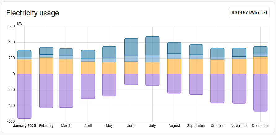
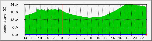
So how has that gone? Courtesy of home assistant I have this pretty chart for 2025:
Combined with the other reporting, what does this tell me?
The total energy i used to get stuff done was 4.32MWh
My solar panels have generated 6.16MWh, I was only able to directly use one third, with 3.97MWh sent to the grid
I pulled 2.13MWh from the grid, 1.57MWh in off-peak and 0.58MWh in peak times
In a summer month I have heaps of excess solar, and overall use less energy (more daylight hours, only use the AC on the hotter days)
For a winter month I directly consume about half the solar, with overall more energy used (mostly because at least one AC unit will be heating a room when I am awake)
What does this translate to on my bills?
Rate
Usage
Cost
Daily charge
$1.15/day
365 days
$419.75
Peak rate
37.2c/kWh
584.41 kWh
$217.40
Off-peak rate
22.3c/kWh
1546.38 kWh
$344.84
Solar rate
3.1c/kWh
-3971.23 kWh
$-123.10
Total:
$858.89
If I look back to 2023 I paid $1,853 for gas and $1,635 for electricity, a total of $3,488. That $858 figure is looking quite nice, it could be said that the changes I made at the end of 2023 (adding solar, removing gas) are saving me $2,500 each year.
I was curious about the impact of solar, so I ran the numbers to estimate what my bills would have been if I had only dropped gas (the addition of AC units) and replaced the hot water system. I likely still would have switched to a time of use tariff and then minimised my usage during peak times, for the calculation I will pro-rata the overall usage:
Rate
Usage
Cost
Daily charge
$1.15/day
365 days
$419.75
Peak rate
37.2c/kWh
1184.57 kWh
$440.66
Off-peak rate
22.3c/kWh
3134.43 kWh
$698.98
Total:
$1559.39
So based on these numbers, getting rid of gas just removed that bill from the equation. While the savings from switching to a heat pump for hot water were taken up by using the AC units (aka other heat pumps) for heating, with the bonus of now having cooling as an option.
So now back to the question of sending excess solar to the grid. In the two years since the installation the feed in tariff has dropped from 6c/kWh to 3c/kWh, if I were to change plans now it is down to a measly 1c/kWh.
So sending excess solar to the grid should be the last resort. I currently try to have all my large usage loads during the day when there is solar which is hot water, the dishwasher, the washing machine, half of my heating/cooling and more than half of my cooking. The remainder of the heating/cooling and cookie is in the evening, when there is no solar.
I don’t have an EV (yet…) but my car usage is mostly local a couple of times a week, so topping off its battery wouldn’t be significant.
So would it make sense to get a home battery?
Using this as my usage pattern:
Average day
Consumption
From grid
From solar
Excess solar
Summer
12.1 kWh
4.4 kWh
7.7 kWh
15.1 kWh
Winter
15.3 kWh
10.2 kWh
5.1 kWh
4.7 kWh
So what type and size of battery would fit with this usage?
I have yet to dig into the details of batteries but I have seen a number of examples using typical sizes of 6kWh and 10kWh. So in summer I could easily charge up a 6kWh or 10kWh battery from solar every day, only needing the capacity of 6kWh for my overnight usage. However in winter I would need a 10kWh battery to handle my overnight usage, which I would not be able to charge up each day.
Assuming I had a suitable battery, what would I save in grid costs?
In summer all my consumption might be able to be covered directly by solar or by the battery charged up by solar. Any pittance I get from excess solar would go towards offsetting the daily charge, in an ideal month the overall bill might be zero.
For a summer month with the ideal case of drawing nothing from the grid:
Rate
No battery
With battery
Usage
Cost
Usage
Cost
Daily charge
$1.15/day
30 days
$34.50
30 days
$34.50
Peak rate
37.2c/kWh
39.6 kWh
$14.73
0.0 kWh
$0.00
Off-peak rate
22.3c/kWh
93.2 kWh
$20.78
0.0 kWh
$0.00
Solar rate
3.1c/kWh
-454.3 kWh
$-14.08
-321.5 kWh
$-9.97
Total:
$55.93
$24.53
That is looking promising, with the monthly bill in summer being halved, but with batteries looking to cost at least $8000, that is a 25 year ROI… and what about a winter month where all the excess solar goes into the battery to offset part of the grid usage?
Rate
No battery
With battery
Usage
Cost
Usage
Cost
Daily charge
$1.15/day
30 days
$34.50
30 days
$34.50
Peak rate
37.2c/kWh
85.3 kWh
$31.73
46.6 kWh
$17.34
Off-peak rate
22.3c/kWh
236.3 kWh
$52.69
128.8 kWh
$28.72
Solar rate
3.1c/kWh
-146.2 kWh
$-4.53
-0 kWh
$0.00
Total:
$114.39
$80.56
Hmmm… I didn’t quite expect for the bill reduction to be around the same, and it might be an artifact of these specific numbers, but with the additional saving being so small it is not looking like a home battery would be a good option for me.
Apart from general chatter in news and other places about batteries, the one thing that triggered my thinking about it was an email from the company that installed my solar panels, I will see what they will suggest (with the awareness that they are trying to sell their services).
The two bedrooms (one I use as my study) in my house (technically a unit) have large windows that face west. This means that they get full afternoon sun which can be a problem in the warmer months. Fortunately there is canvas awnings which do the simple job of keeping the direct sun off the window glass, the first layer of managing temperature.
Despite being the “automatic” type these awnings are operated manually. This naming comes from the 1970s and the awnings are the type on a spring loaded roll that you pull down, then lock in place on arms that extend out. Pulling down on the awning will unlock the arms and the awning rolls back up.
The specific awnings I had were quite old, the canvas had been replaced by the previous owners and at least one mechanism looked like it was possibly original. Basically all the metal parts were either rusting or the paint was flaking off, so it had been on my list for a while to tidy it up in some way.
Until I recently went to use them for the first time this season and one of the plastic end caps disintegrated, making the awning unusable.
So now instead of of background job to tidy them up, I had the more urgent job of getting them replaced before the heat of summer kicked in. So I started to get quotes, but I didn’t just ask for one quote from each installer, I asked for the price to replace with the same automatic awning type and also for a price to replace with a motorized awning.
The quotes were fairly consistent: around $3k for automatic or around $6k for motorized. However that $6k did not include the cost of an electrician running power to each awning.
I also didn’t know what support the motorized awnings would have for integrating with home assistant, because if I was going to get something that could be automated, I wanted it integrated with what I already have.
Them I remembered something, with all the things I have done with home automation, almost everything have been monitoring. The only thing I control is the heating and cooling, mainly to have it on a schedule, and to turn it off if the exterior doors are open. So did I need to automate this? If I am home it is a simple task to pull them down, then later in the day (or if it rains or is very windy) go back out and raise them up.
It was also more than double (remember an electrician wasn’t included) the price, so I stayed with manually operated “automatic” awnings which were installed today:
For a long time I have been intending on monitoring the state of my garage door with my original idea being to use microswitches on the opener mechanism to determine the fully open and fully closed positions. I couldn’t work out a good way to mount the switches so over the years I have considered other options such as a wireless tilt sensor attached to the door.
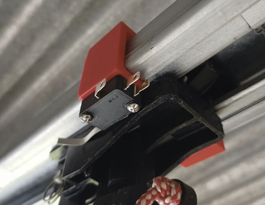
Now that I have a 3D printer I realised that I was now able to design a custom bracket to hold the microswitch:
The clips over the rail for the garage door opener to hold the microswitch against the side of the carriage that is attached to the door. I am using microswitches with long arms that I bend to make sure they cleanly slide along the carriage.
Originally I wrote some code for an arduino to send the status of the door over mqtt, but recently I have been playing more with ESPHome. It doesn’t have the same satisfaction as writing it from scratch, but it sure is a lot easier and quicker.
The two microswitches are set up as binary sensors, which update the status of a template cover:
Over the years I have seen other open source projects for garage doors such as OpenGarage which uses an ultrasonic distance sensor to detect the door position. I don’t like this for door position as I have a single panel tilt door and a distance sensor could tell me if the door is open, but it can’t detect if the door is only slightly open.
But it did get me thinking because another use of the distance sensor is to detect the presence of a car. I picked up some 3.3V sensors (for better long term compatibility over the 5V type) and ESPHome made it simple to add a distance sensor and then a template sensor that uses that distance to know if my car is there or not. It is 2.3m from the sensor to the floor, or 0.9m from the sensor to the roof of the car.
sensor:
  - platform: ultrasonic
    trigger_pin: D5
    echo_pin: D7
    timeout: 4m
    name: "Ultrasonic Sensor"
    id: ultrasonic_sensor
    update_interval: 10s
    filters:
      - filter_out: nan
      - median:
          window_size: 10
          send_every: 6

binary_sensor:
  - platform: template
    name: "Car"
    device_class: presence
    icon: mdi:car
    lambda: |-
      if (id(ultrasonic_sensor).state < 1 && id(ultrasonic_sensor).state > 0.8) {
        // car is in the garage
        return true;
      } else {
        // no car
        return false;
      }
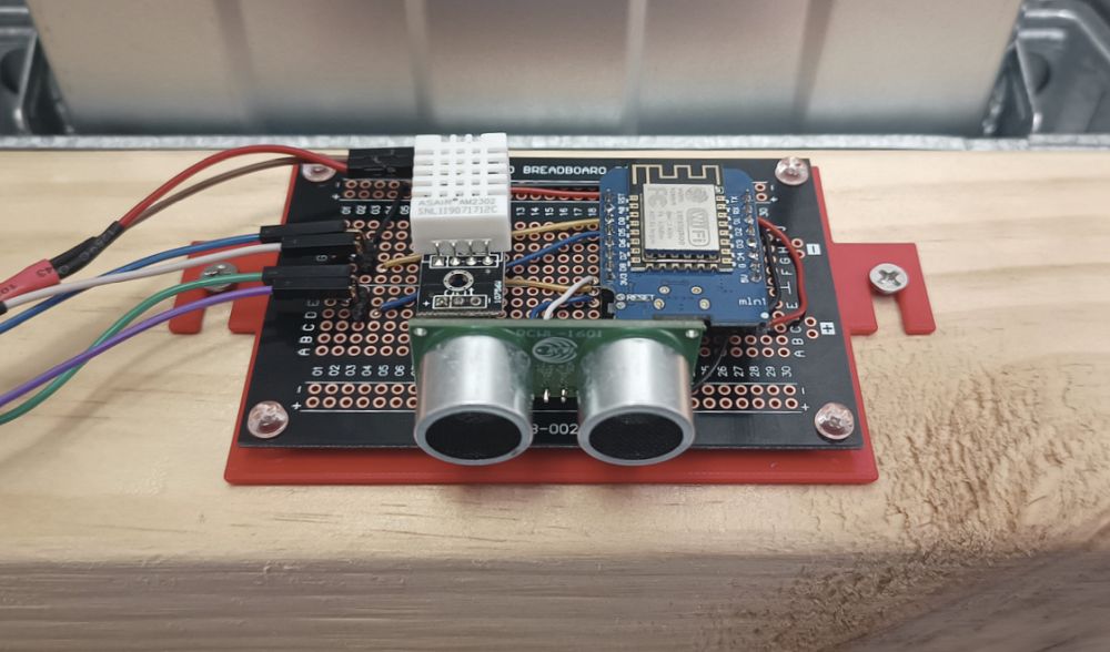
As is my habit I also included a temperature sensor and then wired it up on a protoboard. To mount it to the garage roof I 3D printed a simple bracket:
You may notice that I am not controlling the door. That is because I am only interested in monitoring, I don’t want or need remote access to open the door.
Also with the D1 mini I think I am out of suitable IO to control a relay. Some of the outputs are not stable at boot so shouldn’t be used to control a relay, and those are the best ones to use for the ultrasonic and temperature sensors. Of course this is an issue that is easily solved by upgrading to an ESP32, but before I consider that I need to tidy up the wires and connect them better, possibly designing a custom PCB to hold these components.
In my irregular review of the current electrcity rates I decided that it was time to switch to a time of use plan. The daily charge is lower, the solar feed-in higher, and while the peak rate is higher, that is only six hours of the day with the off peak rate being much lower:
Previous
New
Daily charge
$1.08/day
$1.03/day
Peak rate
27c/kWh
29c/kWh
Off-peak rate
N/A
17c/kWh
Solar rate
4c/kWh
6c/kWh
I could possibly pull the data form Home Assistant or from the Enphase portal, but through my energy distributor I can download a CSV report of my usage going back years. I don’t recall the exact format but this one is in one day per row, then with the usage (as reported/charged by the meter) in half hour blocks.
Calculating what my bill would have been for the past few months showed that I would have paid at least 20% less, so I updated my plan.
I now needed to work out how to have Home Assistant split the power usage and cost between peak (3PM to 9PM) and off-peak (all other times). I quickly learned about the Utility Meter integration and I followed this video/post to get it set up.
This is when I encountered a problem in Home Assistant that was not easy to figure out. Most of the time Home Assistant works and does what I want because I am not doing anything unusual, but when you hit that unusual case it is quite painful…
What was I trying to do that was unusual?
Back when I configured the energy monitoring I set up two sensors, one for import energy and one for export energy. It is these that the energy dashboard uses and it is against those that the long term history is stored.
With the import sensor split into two (peak and off-peak) I could add these to the energy dashboard and set their appropriate rates, but if I removed the existing import sensor then I would lose the history from that sensor. I couldn’t have the existing sensor and the new sensors in the energy dashboard as then it would be reporting double.
I wanted to keep the existing sensor, but somehow transfer its history over to the new peak sensor. This is apparently possible to do with some strategic renaming of the sensors, but despite following different sets of instructions I couldn’t get it to work. The more common instructions appear to now be incorrect due to changes of how renaming sensors will also move around their history.
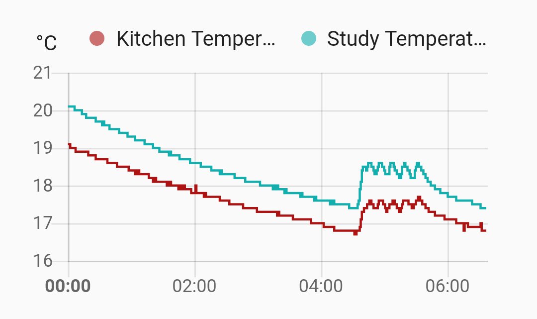
I spent more time that I wanted reading through reddit and forum posts, but in the end I worked out enough about how the long term statistics tables work to be able to copy all of the history from the existing import sensor over to the new peak import sensor, so now I have graphs that show two shades of blue:
Where this will be more useful is in the longer term views:
Of course there is still the question of why don’t I switch to Amber to get the variable wholesale rate? At this staged I am not comfortable making that leap, what would make me more comfortable is being able to get a few months of historical price data that I can them apply to my actual usage…
For a while now I have had a couple of AirGradient Air Quality Monitors as part of my home automation. One has been mounted to the wall near my desk and has been quite interesting seeing how the CO2 levels change throughout the day, especially when I have the study door closed. The other is the outdoor model which I got to have a more reliable outdoor device and also so I can compare the levels of particulates between my study and the wider world.
A few months ago they announced that the latest firmware would have direct integration with Home Assistant. This weekend I finally got around to checking that out, but it had a few rough edges.
Reverting to the latest stock firmware was easy, it was possible to do over USB directly from the browser. The only tricky part is that I didn’t want to take down the outdoor unit, so a long cable and my laptop was the answer there.
Once they were reflashed I could see in their log that they were working, but I was a bit stuck as there was no obvious next step. They were connected to my network, but there was no automatic discovery in Home Assistant.
I am running Home Assistant in a non standard way (via docker so I only have core features) so having to add devices manually is not unexpected, but if I tried to go to the web interface the devices exposed all I got was:
Not found: /
Was this correct? Did it not reflash correctly?
The first thing I came across was that there is MQTT support. Ah, maybe that is how they communicate with Home Assistant?
However the information on enabling MQTT said it was via the dashboard, but my devices are not connected to the cloud dashboard, I don’t even have an account there…
More stumbling around led me to a forum post and the Local Server API documentation. Now I knew to hit the /config endpoint I could see and change the settings and now they were reporting to MQTT.
Still no auto discovery in Home Assistant… so I did something I should have tried earlier, adding the integration manually with the ip addresses of the devices. This worked.
It turns out that I didn’t need to enabled MQTT, but I have left that enabled as I log all the MQTT messages, so it might be useful for debugging.
I also need to raise a ticket, that Not found: / was not helpful. If a device exposes a webserver then hitting to root endpoint should give something useful about the device, it doesn’t need to be a fancy status page, it could simply be a static link to relevant documentation…
After my recent incident with my front door being open unexpectedly I started to look into Zigbee and Z-Wave devices for integration into Home Assistant. I quickly started to lean towards Zigbee for both price and ease of use reasons, but I was going to take it slow in case I did pivot to using Z-Wave.
(side note: while technically Zigbee is used to get data from my smart meter, that is a custom/closed interface that I cannot access)
To get started I ordered a Zigbee gateway, a couple of Sonoff door sensors, and also stopped by Ikea to pick up a couple of their door sensors. While there I also saw their motion/light sensor, so grabbed one of those.
When the gateway arrived I set it up on my wifi and then pointed the ZHA integration in Home Assistant at it. This worked but it felt quite slow and clunky. After doing some more reading I learned that they recommended against using serial-to-IP over wifi, exactly what I was doing.
My next setup was to bring up a container for Zigbee2MQTT connecting to the same Zigbee gateway. This was a much nicer experience so that is what I went with… for a few days. While initially this would work and respond immediately to the door sensor or motion sensor, after a couple of days it became less reliable, sometimes just dropping out and requiring both the gateway and container to be restarted.
I realised I needed to simplify the connection between Zigbee2MQTT and the gateway, make it as direct as possible. Looking at available options I decided on a SMLIGHT SLZB-07p7 Zigbee coordinator which has a USB connection, meaning as direct serial connection as possible between zigbee2mqtt and the gateway/coordinator as possible.
However I was running Zigbee2MQTT in a container on the linux box in my study, this is not the best location for the Zigbee coordinator, I still wanted that central to my house which means the laundry (where I had placed the first Zigbee gateway). So how to solve this? With a Pi 3 model A+ as I used for the RAVEn smart meter dongle:
I have read that there might be interference between the Zigbee and wifi for this configuration, but that can be reduced by spacing them out with a short USB extension cable. For now it has been working quite well, but as always, time will tell…
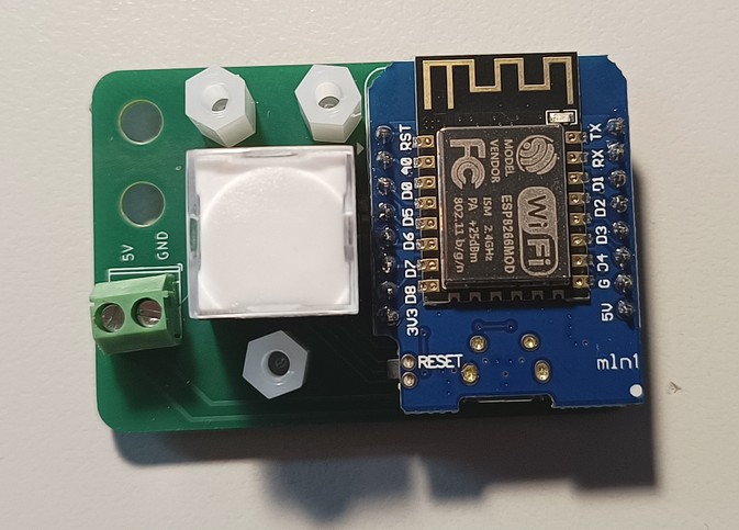
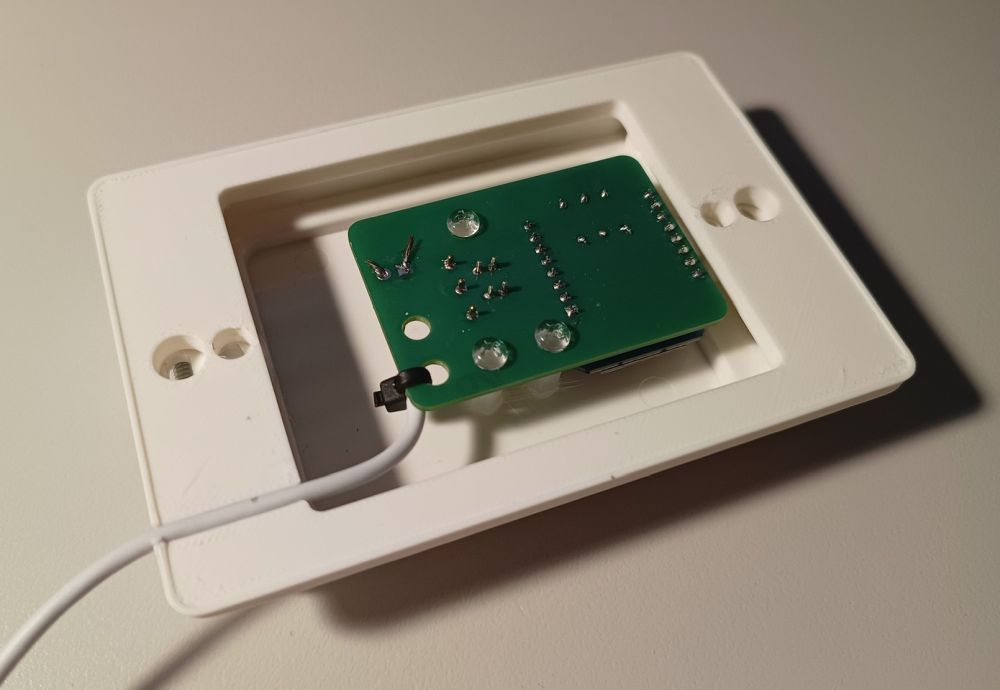
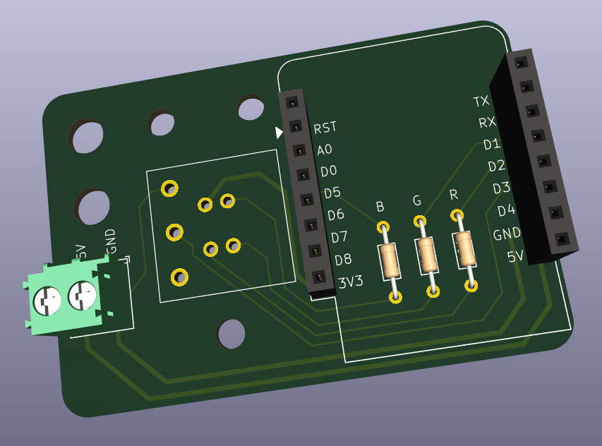
The green terminal block ended up being too tall for what I wanted, so that was removed. The three nylon spacers are what will be glued to the back of the faceplate.
It is not visible, but I found low profile pin headers, these keep the D1 mini as close to the PCB as possible, but without directly soldering it in place in case I need to swap it out.
This is all still too thick for a single faceplate so a spacer block is still needed, but as I now have a 3d printer I am not limited to the spacer blocks you can buy, I was able to design and print a simple spacer that also includes a channel for the power wire to pass through:
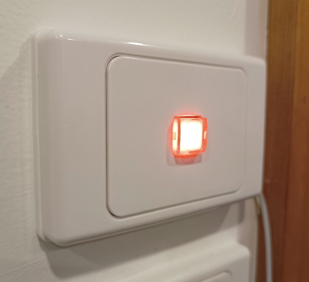
Final result:
I now need to refine the automation rules in home assistant. I’m thinking seomthing like red for power has been turned on, blue for dishwasher is using power then green for when the dishwasher has stopped using power and is ready to empty.
I will probably also set up another panel for my washing machine.
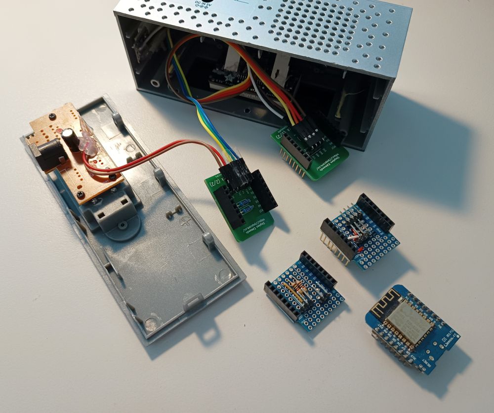
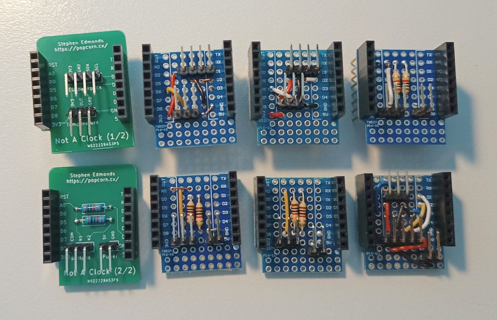
I was able to compare the new PCBs against the ones I had soldered up on protoshields at various times:
Now that the boards were all the same I was now able to connect up the buttons on all of the not a clocks, but I also found that at I hadn’t been consistent with the pin assignments, so I also flashed them all to be the latest version.
Once my shiny new PCBs arrived I soldered up one of each type to confirm that I hadn’t made any mistakes. Thankfully they are all very simple and I had checked them over multiple times before submitting the order.
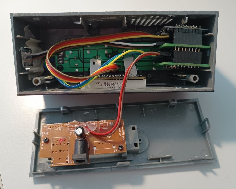
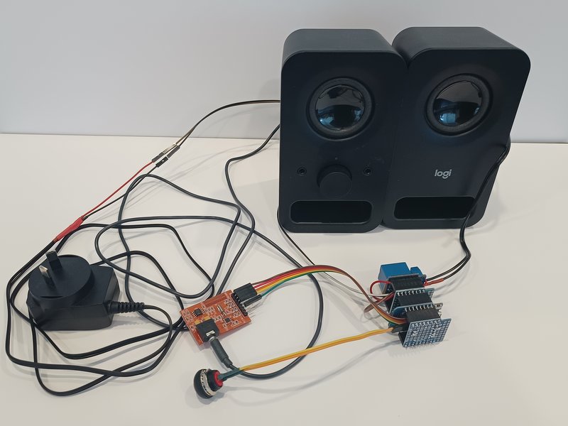
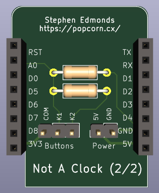
As one of the designs is for my MQTT controlled FM radio I was immediately able to switch from prototype:
To a more refined version:
There is still a bundle of wires between this board and the speakers, but a future project on my list is to rework this, probably with a new 3d printed case to have it all as a single unit.
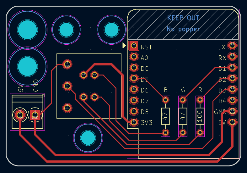
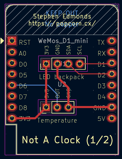
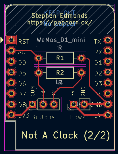
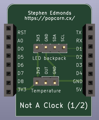
After the success of designing and ordering my first custom PCB I continued on with designing a board to hold the RGB button and microcontroller behind the faceplate. This time I was able to use existing footprints for the D1 mini, resistors and a terminal block for power:
When I went to order these boards I realised that postage for a small order was most of the cost, but I could add other boards to the same order for the same postage cost. I was already planning on adding another not a clock to the lounge room, so why not order boards for that instead of hand soldering more proto boards:
I maintained the same D1 sheild PCB size as that fits nicely within the clock enclosure and I did try designing the two pieces to be a single board that you would break into two, but I couldn’t quite figure that out, so separate boards was the end result.
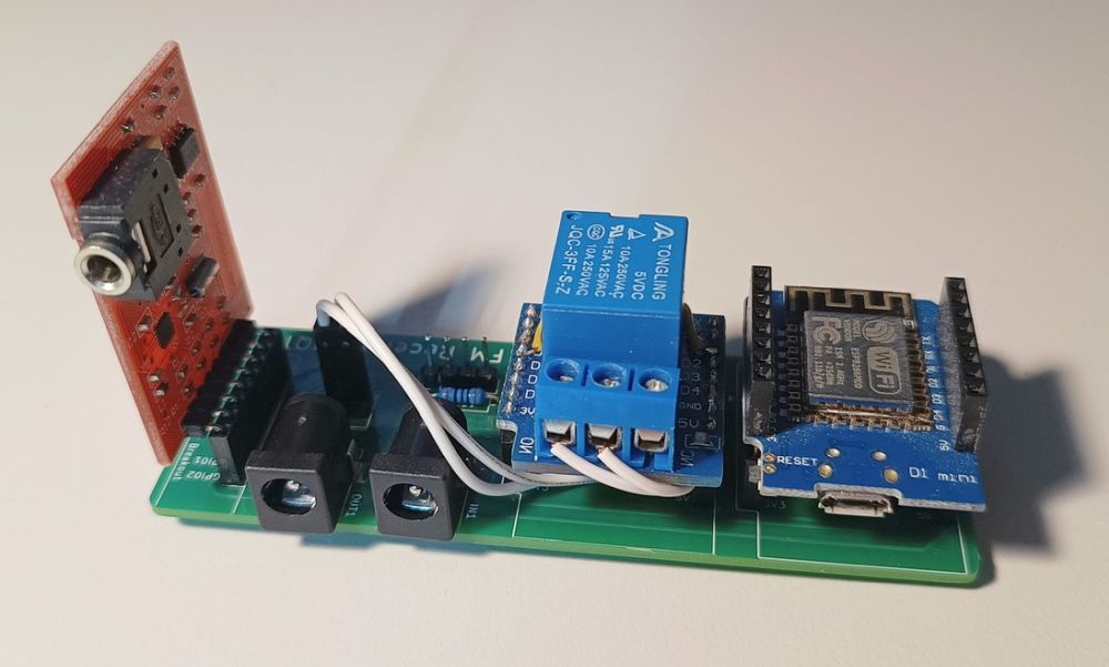
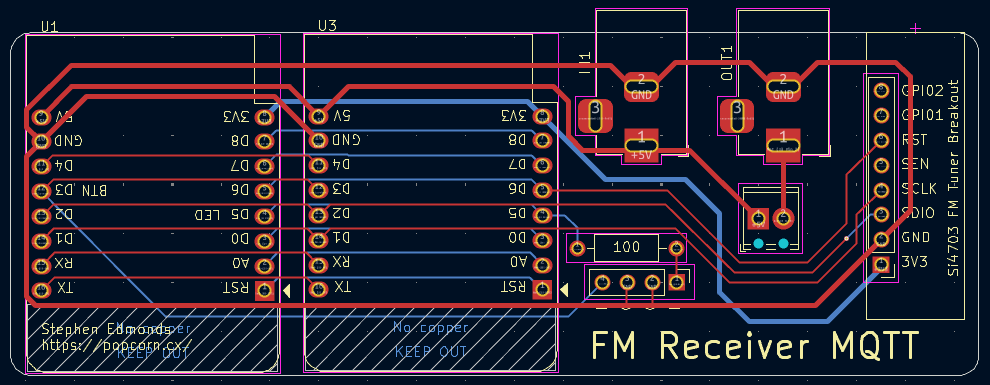
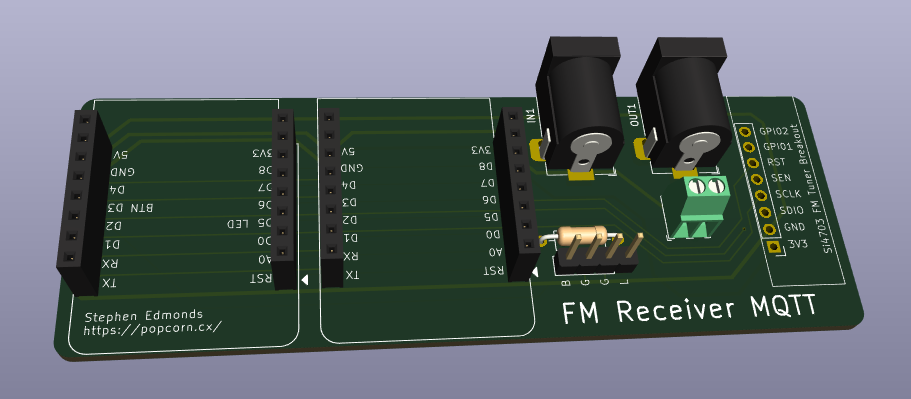
As I was getting more comfortable with KiCad I moved on to a more ambitious (for me) project, a PCB for my MQTT controlled FM radio. At this point I decided to keep using the relay shield, so I needed two sets of D1 mini headers, power in, power out via the relay, a button, an LED indicator and of course the FM module:
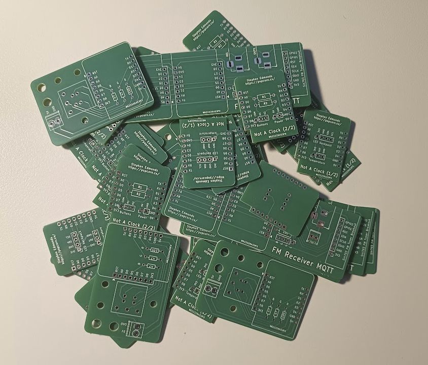
I felt that four different PCB designs was enough to split the postage over, so I submitted the order and today received a satisfying delivery:
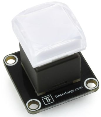
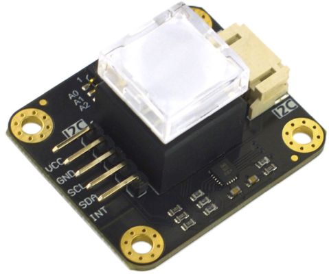
Every so often I would look into options for making it less obtrusive when mounted to the wall and I came across two options for RGB buttons that I was thinking I could mount into a wall plate:
These were looking promising, until I got to the price… €14.99 and US$9.90 each which meant that I continued looking.
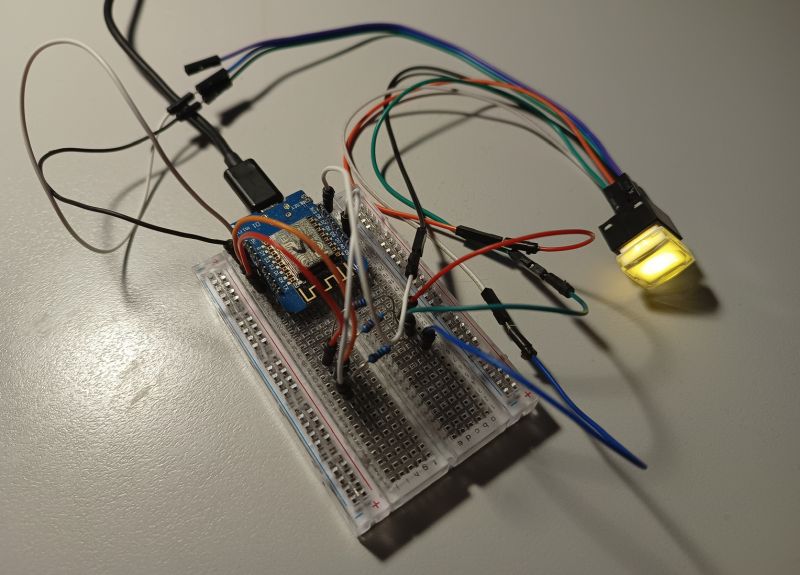
I don’t know what I was searching for, but I stumbled across some RGB illuminated buttons on ebay and as I could get six of those for the price of the above buttons I decided to give them a try. So after a week or so of wating they arrived and I was able to quickly hack together a proof on concept:
This is a D1 mini running ESPHome, the button press is a simple button input while the LED is using three output pins for the discrete red, green and blue LEDs within it. This was a quite tenuous setup with the leads just shoved over the (different sized) pins of the RGB button. I needed to have a better connection, and also a way to mount it.
Like the two ready-made buttons I needed to mount this to a small PCB, but where would I be able to find one? Could I make something out of breadboard?
Or do I finally do that thing I had heard other people do? Design and order by own custom PCB?
I didn’t really know where to start, the first tool that I found which didn’t require an online account was KiCad. That was a tool that I had heard of, and I saw that it had a plugin to export to PCBWay, which a PCB company that I had heard of.
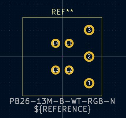
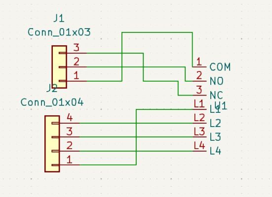
I definitely didn’t start this off easy because I couldn’t find these RGB Buttons as an existing part within KiCad, however the ebay listing did include specifications so I headed off down the path of creating my own footprint (the physical layout of the part) and then using that on a board.
From this information:
I created the footprint for the part:
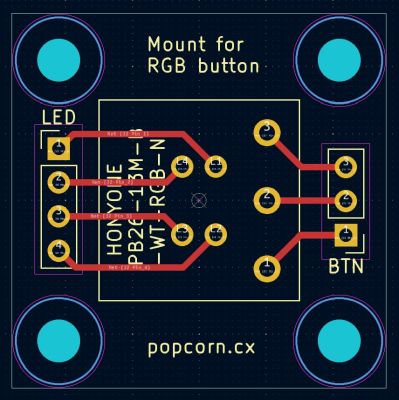
Added it to a schematic and laid that out on a pcb:
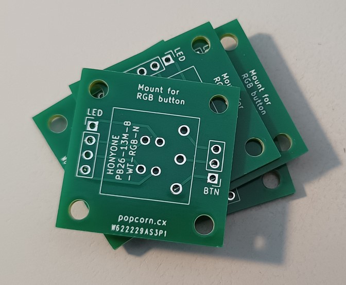
Waited a week for a parcel to arrive containing a small stack of green circuit boards:
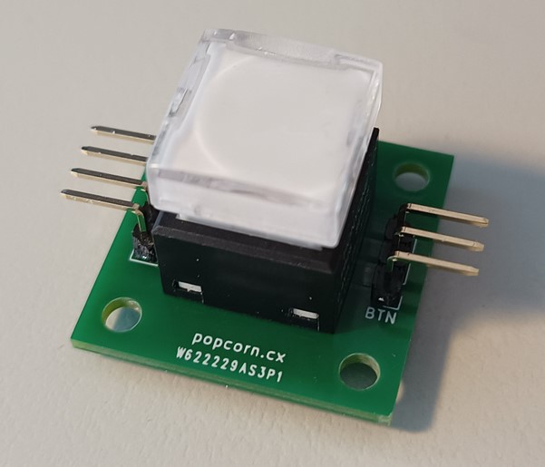
Onto which I quickly soldered on an RGB button and headers:
The idea was to use the four holes in the corners for standoffs that would be glued to the back of a blank faceplate with a suitable hole cut out. I didn’t bother with glue but did cut a hole and was able to preview what it would look like:
That will blend in a lot more than the current blue PCB. I’m not going to use this as is, I’m considering a proof of concept as I think I can design a board that holds the RGB button as well as a D1 mini, why try to wire up components behind the faceplate when the PCB can do that for me…
My interest in home automation has always been more around monitoring than automation, and also doing it locally. I have never felt the need to be able to turn lights on and off via my phone when I am at home, let along if I am away from home. However there have been a couple of times when I have wanted to check on something remotely.
I was not going to expose my home assistant instance to the world and I didn’t want to set up a permanent remote access method, however I remembered that my home router is WRT based and can run an OpenVPN server. I can then install the OpenVPN client on my phone or laptop, giving me remote access to my network (so not just home assistant) if I needed it.
Right now I am in a hotel room in Gladstone, Queensland. The second Everything Open conference ended yesterday (hopefully I will write up a report on that soon) but I do not fly home until tomorrow. So it was a bit confusing to get a phone call from my neighbour, asking if I was home early, because my front door was wide open…
That is not a good thing to hear, so I asked them to cautiously investigate as they have a key. They found that the laundry screen door and door were both still locked, there was no signs of disturbance. The front screen door was still locked and despite being open the front deadlock was still deadlocked.
My first flight of the day to head up to Gladstone had been at 6am, so I had left home at 4am. My best theory is that as I was locking the doors in the dark that I didn’t quite pull the front door enough and it didn’t latch, then strong wind a few days later was enough to open it all the way.
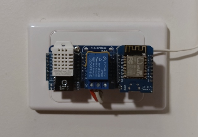
The sensor on the laundry door is a reed switch connected to the arduino that is also monitoring the temperature in the laundry and also the outside temperature. There is power nearby so I don’t have to worry about batteries. There is no power convenient to my front door (or other similar locations) so I have been thinking about something battery powered. An arduino uses to much power, but maybe it is time to look into Zibgee or Z-Wave devices?
The first major issue was not that long after I set this up, the radio station I had chosen decided to change their main stream over to HLS which it turns out my speaker does not support. I tried to work out if there was a proxy I could use (or make) to covert HLS back to the older style, but then managed to locate an alternate stream for the same radio station.
An intermittent issue, but happening more in recent weeks, is that sometimes the stream doesn’t start, or the stream will start but then after a time will stop. I can see from the Home Assistant logs that it does start but then falls back to “buffering” and then off. I’m thinking that this is a network timeout or other issue.
I have also been looking out for a new speaker for the kitchen, but here it is not for streaming the radio, but for playing podcasts from my phone via bluetooth. The cheap speaker I have now doesn’t always connect to my phone and I want something mains powered so I don’t have to remember to turn it off to make the battery last as long as possible between recharges.
As I was struggling to find a non-portable bluetooth speaker for the kitchen I started thinking about a cheap mini hifi that had bluetooth. That thought evolved into what able using that for my alarm because I now have an IR blaster to control my AC unit, that could also send commands to a mini hifi.
Looking though parts I have picked up over the years I came across the Si4703 FM tuner board, what if I revisited that idea? It would better integrate into Home Assistant as it could give current status that an IR blaster cannot do. These thoughts felt familiar, so I looked back at my post from five years ago. Huh. These are all options I looked into back then…
Instead of spending money on a mini hifi I realised that already had the parts I needed. The FM tuner board and a spare set of computer speakers could be the alarm, then the current chromecast speaker could be moved to the kitchen and used directly with bluetooth. What really made this come together is this video from two months ago:
It is looking like the example code from the video will do almost what I want. I might go through and strip out the serial control and OTA update functionality that I’m not going to use, but apart from tweaking some of the defaults and adding in control of a relay I think the software side might be sorted, including a panel within Home Assistant that I have updated with local station presets.
I have been using this for around two weeks now, it is working quite well so I should get around to tidying it up into a project box.
A few days ago I mentioned how I had reflashed two Sensibo Sky devices with ESPHome as I prefer that arrangement for controlling my AC units. As there were some gaps in the instructions I found on reddit I decided to fully document my steps here. This may not be the best or only method, but it is what I did.
Once I picked up the devices my first challenge was actually opening them up. The reddit post didn’t have any information, I couldn’t see any obvious way and a quick search didn’t turn up anything. I briefly considered just trying to use the exposed pins, but I didn’t know what type of connector and didn’t want to wait, so I turned to my iFixit toolkit, using a couple of the plastic picks to wedge open the white casing from the USB port side.
It turns out this was unnecessary and the case is very easy to open.
The translucent part of the case has a hook that clips into the white part, so if you push down on the Sensibo logo you can slide the white part down slightly and it will then lift off. The translucent part can then be unclipped.
UART GND to Sensibo pins 0 and 15 (though apparently only 0 is required)
I then powered up the device using the USB port, previously the LED would flash when turned on, now it was on solid.
To confirm that I had a connection I used esptool:
$ esptool flash_id
esptool.py v2.8
Found 1 serial ports
Serial port /dev/ttyUSB0
Connecting...
Detecting chip type... ESP8266
Chip is ESP8266EX
Features: WiFi
Crystal is 26MHz
MAC: c8:c9:a3:a5:d7:16
Enabling default SPI flash mode...
Manufacturer: eb
Device: 6015
Detected flash size: 2MB
Hard resetting via RTS pin...
Satisfied I was able to connect I now went into the ESPHome Dashboard and created a new device, this didn’t have any sensors yet, just enough configuration to connect to my wifi (with a static IP because I find that easier than hoping mDNS will work).
As I was doing this from my main desktop and not the machine the TTL UART was connected to I opted for the Manual Download of the firmware. After doing its thing the dashboard gave me an image file to flash.
As I had used esptool to check the connection, I used it again but now to flash the new image. I didn’t keep a copy of the output but the command was:
$ esptool write_flash 0x0 bedroom_ac.bin
The flashing said that it had completed successfully so I disconnected all the wires from the Sensibo and then powered it up from just the USB connector. I breathed a sign of relief when the ESPHome Dashboard showed the device was ONLINE and I could look at its logs.
On the reddit post are two main ESPHome configs, one from the original author and then another linked in a comment. I used a mix of both of those to end up with my current configuration:
One big difference was that I used friendlyname and that I configured the LED to be on when the climate platform is also on and also be the statusled. The button currently has no action (I need to drill out the case and extend the physical button so it can be used) and I also like having uptime and wifi diagnostics.
With one device converted for use in my bedroom, I then repeated the process for the one in my study.
In addition to thinking about a housing for my dishwasher panel I have been looking into a housing for my AC controllers which currently look like:
(yes I know I should have cleaned off the dust before taking the photo, but that was a quick photo taken for a talk at work)
What could the housing be? Do I base it around another wall plate? Do I get a wall mounted project box? Do I buy my first 3d printer?
After my experience with the dishwasher panel I also realised that as this is based on ESPHome, so I could add an indicator LED (red for heating, blue for cooling?) and a button (to quickly switch between a standard preset such as 24°C cooling and turning it off). These would also need to be incorporated into the housing.
In my looking around I found that the housing I wanted does exist, in the form of the Sensibo Sky. While there is Home Assistant integration I prefer a non-cloud solution and I already had that up and running.
I don’t know exactly how I came across it but I found a reddit thread showing how the Sensibo Sky is based on an ESP and had instructions on how to flash ESPHome onto it. This was an intriguing idea, but I wasn’t going to buy two Sensibo Sky units just to reflash them.
(yes, it is always appropriate to spend 20 minutes watching Randy describe buying a bookshelf on Gumtree, 46:25 into Randy Writes a Novel)
eBay was no help, but on Gumtree I found something. While I was looking for used or broken units, what I found was someone not that far away selling two unused units for less than the price of a single unit. Sold! I picked them up the next day and thanks to the reddit instructions (I will make a separate post with my full steps) I was able to flash them with ESPHome.
A bit of reconfiguring within Home Assistant and these are now my AC controllers. I even have them mounted to the wall so they don’t take up desk or bedside table space.
While the built in LED is only blue I did configure it to indicate if the AC was currently on and I think I have a plan for the button. Normally this button is used to reset the Sensibo Sky to factory defaults which means that you use a pin through a small hole in the casing, but I think I could drill out that hole and then glue an extension onto the button, giving me the shortcut action trigger.
Could I go further with some of the pins that are exposed. Is is possible to replace or supplement the LED with an RGB version? Could I mount a button on the face of the unit instead of the side? These are all options opened up by the flexibility of running ESPHome ;)
When the previous owners of my place renovated the kitchen they put the power for the dishwasher directly behind the dishwasher instead of the correct location in an adjacent cupboard. This didn’t directly affect me until that dishwasher needed replacing and there was now not enough clearance for the plug.
I replaced the dishwasher over two years ago and my temporary solution was to have the cable coming out of a gap in the side panel and up to a power point above the bench. Last week I finally had an electrician in for a couple of changes which included replacing the kitchen downlights (from 300W of halogen to 48W of LED), replacing a failing bathroom exhaust fan and adding a power point to the cupboard next to the dishwasher.
However this meant that the Tasmota based smart power plug is now also located in the cupboard. I could no longer hit the button on it to turn on power to the dishwasher.
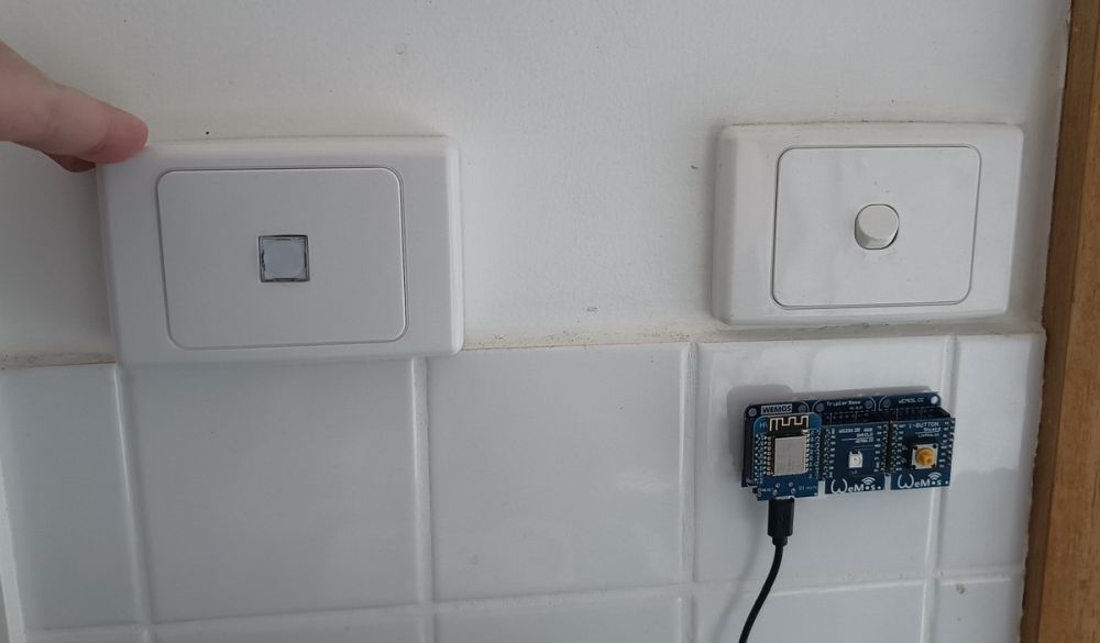
So I started to think about some kind of remote panel button/display that could be mounted on the wall above the dishwasher. As I am still building my projects around the D1 mini I was able to put this together from the variety of shields and bases I picked up a while back:
Unlike my clocks where I wrote a minimal program that communicated via MQTT, this time I decided to try setting this up using ESPHome which I had used to interface with my AC units. It was only a few minutes until I had a button and an RGV light showing up in Home Assistant.
I now started on the more complicated part which was deciding what logic I wanted and then implementing it as automations. So far I have the following:
First is the action to take if the button is pressed:
if power is off, then turn on power
if power is on AND dishwasher not active, then turn off power
Then the behaviour of the LED:
if power is off, then LED is off
if power is on:
if dishwasher active, then LED is blue
if dishwasher has been active since the power was last turned on, then LED is green
if dishwasher has not been active since the power was last turned on, then LED is red
I can now see at a glance if the dishwasher is running, if it needs emptying or if it is on and shouldn’t be. The next step will be to work out an enclosure, I am leaning towards something based around a wall plate and spacer block like I did for my bathroom clock/sensor:
I’m thinking of a small hole for a button to protrude through, and then see how well the LED just shows through the plastic.
There are plate that exist for commercial applications for things like running AC after hours that are a push button and a neon indicator in a two gang plate, but those are quite large (in depth as they are intended to mount in the wall, not on the surface of tiles like I want) and also very expensive, even if all I wanted was the housing for the neon indicator that I would retrofit the LED into…
So far this summer the weather has been pretty mild so it is odd to think that we are now in February and this is the first time that we have had temperatures in the high thirties. Based on my measurements we reached 36.2°C yesterday and 38.4°C today.
I am still working out how I want the schedules and automation to work, but so far I have it that a calendar entry for 24#COOL#STUDY means that I will allow the study unit to be running at 24°C in cooling mode. The automation looks at the current outside and indoor temperatures and will not start the AC until they both reach 24°C
On Saturday that condition was met at 2PM and kept my study at a nice comfortable temperature. I also closed the exterior blinds and had the ceiling fan on low. Today that condition was met at 10:30AM and things also remained comfortable, though since there was plenty of sun I also turned on the bedroom AC unit and lowered them both to 22°C to see how that felt.
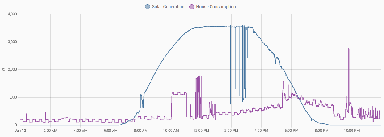
Speaking of sun… it was a nice clear day and the generation from my solar panels was the stereotypical ideal curve:
Consumption items of note are:
hot water running for an hour from 9AM
spikes at 10:30AM when I cooked an early lunch
increasing usage with the AC at 24°C and then further increase when both running at 22°C
spikes in early afternoon when I use the washing machine
a drop at 5PM when I switched back to one AC at 24°C
It is nice that most of this usage is covered by solar generation. The stats for the day so far are:
29.6kWh solar generation
15.2kWh consumed
4.2kWh pulled from the grid
18.5kWh fed to the grid
The reconfiguration of my account for solar finally got done a week ago, so now I am getting credit for what I feed back to the grid. For this day at my current rates the consumption balances the feed-in, making the cost just the daily supply charge. However this is just one day and it is the impact over time that is more important.
I also noticed something odd when looking at the generation from the inverters on each of the solar panels:
So ten of the panels are generating as you would expect for a clear sunny day. But what is up with the other two? In the enphase app the panels are laid out over an aerial image of my roof and I could see that the two panels with slightly lower generation are the two that are next to my tv antenna. So the slight shadow that casts is affecting those panels, changing from one to the other as the shadow changes. While I don’t watch free to air tv often, I won’t get rid of the antenna as there are a couple of shows I still automatically record to watch later.
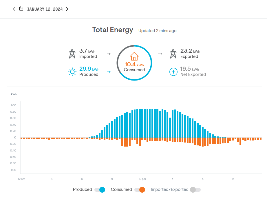
The cloud based monitoring that the Envoy controller reports to gives a status page, but I find the energy reporting to be more interesting. This is the report for yesterday:
There were clouds a couple of times but otherwise it was sunny, so there is a nice curve to the solar production. On the consumption side you can see there at 10am the hot water was on for an hour, then I was cooking lunch with my air fryer at 11:30am. It was a warm day so in the afternoon I turned on the air conditioning to keep things cool.
With the integration into Home Assistant I can get a similar view of the same data through the energy dashboard, though not as granular as it is in one hour (instead of 15 minute) increments:
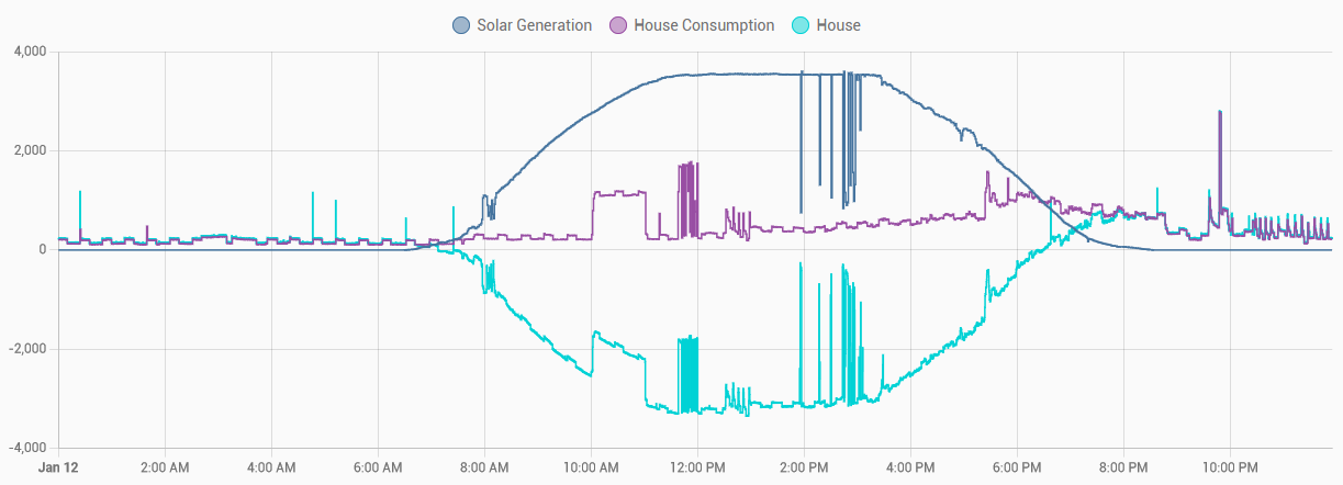
This is getting its data from the “energy production/consumption today” values which are in kWh and reset each day. If I want live information I look at the power values which I have converted to W to be in line with what I get directly from the smart meter, from my UPS and from my tamsota devices. The same day but the power reading which is updated every minute looks like:
It starts to get messy but I can also include the power reading data from the smart meter (updated every 8 seconds):
If the smart meter reading is positive then I am consuming from the grid, while if it is negative then I am feeding power back to the grid. Of course I am still waiting for my meter/account to be reconfigured so I get paid for what I export…
It is clear that on a sunny day in summer that my solar generation will easily cover the large loads such as hot water, dishwasher, washing machine and lunchtime cooking. What would the numbers look like on my bill?
Daily charge:
1
x
107.03c/day
=
$1.07
Consumption:
3.7kWh
x
22.66c/kWh
=
$0.84
Feed-in:
23.2kWh
x
-5.40c/kWh
=
-$1.26
Total:
$0.65
Not as much of a saving as I expected, but this is only a single day and I was running both AC units as an experiment while I would ideally just be running the one in my study. Definitely need to wait and see how the numbers fall for a full monthly billing cycle…
It has been two months since I started to think more about my energy usage and now my energy profile has completely changed. Two weeks ago the air conditioning units were installed, but I have not yet mentioned that yesterday I had solar panels installed and today they completed the install of a heat pump hot water system.
The shape of my roof is not the easiest for solar panels, but they managed to fit twelve panels facing north. The panels are each 370W while the microinverters are 295VA (see this video) which even on an overcast day should cover my typical usage. The system has been running for 24 hours now (technically I should now turn it off and wait for the inspection) and it has been interesting to watch how much they generate versus what the weather is doing.
I opted for microinverters from Enphase (the only option in Australia for microinverters) because I like the idea better than string inverters and the tipping point was that there is an integration included in Home Assistant. So while it is good to have the provided online interface, it was also nice to be able to easily add the solar system. Once added I had thirteen new devices. One for the Envoy which is the controller/gateway, and then each individual panel. The figures I will be interested in are the panel generation, my consumption and how much I feed back to the grid.
My first side quest was to figure out why my smart meter was now saying I was consuming an amount of power that was simply not possible:
As I worked my way through the source of this number I quickly spotted the problem. The number in the XML from the smart meter adapter is in hex and very large numbers start with lots of F. Thinking back to computer science subjects at uni I remembered that is likely a negative number if we are dealing with a signed integer. After some number conversion a demand value of 0xfffffc09 was now coming back as -1015 which is both sensible and aligned with what the Envoy said I was feeding back into the grid. As I had published the script for this to github, it was right to push a fix.
While there was still some daylight (and there was some generation from the panels) I then played around some more in Home Assistant, including enabling the energy dashboard, but that is going to be a longer term task.
As well as installing the solar system yesterday, the electricians also did their part of the install for the new heat pump hot water system. Ready for plumbers to come today to decomission the old hot water system in the roof (still working after 50+ years…) and hook up the new heat pump and storage tank. Its power usage would have been high today as it was heating up the entire tank but once things settle down I will try to record how much it needs day to day.
The piece missing from the hot water install is the wifi module, once they come back to install that I will have a new source of data. There is no out of the box integration as there was for the Envoy system, but I hope I can figure out a way to extract data.
However a much more immediate result is that I have now had the first shower in this house with mains pressure hot water, no more low pressure due to the gravity fed system…
After my recent posts about the cost of natural gas and how I want to heat and cool my home I got a couple of quotes on installing split system air conditioners in my bedroom and study, the paid the deposit for one which was scheduled to be installed on 20 December, just before Christmas.
Yesterday I got a phone call in the early afternoon saying that they had had some schedule changes and could they start the installation that day with it being completed the next morning. I said yes and long story short I now have air conditioning.
The cheapest way to install a split system is “back to back” which is where the outdoor unit is on the immediate other side of the wall to the indoor unit. This was ok for my bedroom because the outdoor unit would be in the gap between my house and garage, but not ok for my study as that would put the outdoor unit on the north facing wall leading to my front door. I was happy to pay the bit extra for the longer lines and labour to put that outdoor unit over next to the other one.
It is getting quite busy over that side of my house, there is the (now unused) central heating, the two new air conditioner units and soon there will be a new hot water tank and heater.
There is nothing special to say about the units I got, they are Fujitsu with decent energy ratings. I opted to not get any wifi interface as I planned to use an integration with Home Assistant that would send IR commands, in particular the ESPHome IR Remote Climate component.
While I could build and IR receiver/transmitter out of parts, the easier and quicker option was to order a couple of IR Controller Shields, they arrived last week and I started playing around with general IR control (that is another post about replacing the universal remote for my TV/etc) and specifically what ESPHome is like to use. Unsurprisingly it was pretty easy if you are familiar with Linux, Arduino and Home Assistant.
Now onto the hard part which is working out how I want things automated. With the central heating it was a simple thing of “make the whole house this target temperature”, but now the heating or cooling will be set for a specific room. Do I want to take the chill off my bedroom for when I get up, then turn off the bedroom unit while I am working in my study, then finally turning the bedroom back on for when I go to bed? Or just leave the bedroom unit off entirely, only using it on the really hot days?
It is also a convenient week to get it installed as despite tomorrow being the “start of summer” the weather has been below 20°C for the last couple and new few days, then jumping to 33°C mid next week. So I get to experience a range of temperatures and how the systems behave.
One other side effect was due to the layout of my study:
While they said they could possibly work over the desk if I cleared a space, I decided that a deep clean behind my desk was overdue so I moved all the NASA LEGO, the printer, the drawers and the desk extensions out so I could pull the desk away from the wall. Giving them room to install the unit and giving me access to clean out the dust and spiderwebs…
After working through the cost of heating water my next target of investigation was appliances.
I am going to consider a fridge (or also a standalone freezer) to be part of the background usage. It is an appliance that needs to run all the time and be reliable because I do not want spoiled food. I am not considering trying to control it, if it is using too much power then the option is to replace it with a newer more efficient model.
Some other large kitchen appliances are the oven and hotplate. I know how much power they use and I know that I mostly use them around lunchtime which is already in “off-peak” classification. The smaller kitchen appliances such as the toaster and microwave are not used on a regular basis so I am not going to worry about those. The dishwasher I will come back to later…
Appliances for entertainment such as the television and speakers are used for specific purposes. I should check their standby usage, but otherwise I am not concerned.
I know the computers and monitors in my study are a large portion of my regular power usage, but they are essential, either they need to be on because I am working from home, or they are on because I am using them for personal projects or entertainment.
So now we come to the washing machine and are back to the dishwasher. These two applicances have pumps or motors, but also heat water which takes a lot of energy. This has been in the back of my mind for a long time, so in order to find out I went to Bunnings and picked up a “smart plug” that also included energy monitoring.
It worked and I was able to get data into home assistant, but this device needed an account on a cloud service to be configured and then the home assistant integration hooked in via that. Not the self contained approach I prefer.
I have yet to return this plug to Bunnings, but I after seem a couple of mentions in forums and other loactions I did order two Athom plugs with AU sockets. Although I haven’t looked at Tasmota for a while I knew of it, and importantly I knew it was MQTT based which I liked.
It took a couple of days for them to arrive and I set one up for my dishwasher and other for my washing machine.
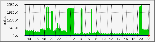
I estimate that I run the dishwasher every two or three days, and this is its power consumption on the “speed perfect” and “half load” setting:
These days with working from home I find that I am only doing a load of washing once a week for clothes, then a dedicated wash for sheets or towels. This is my washing machine on an “intensive” cycle which is what I use for towels:
Quite different patterns. You can definitely see when they are heating water, and I think the irregularity with the washing machine is due to how it is detecting the motor usage, compared to a pump in the dishwasher.
But what does this tell me? Not really much…
But what might I be able to do with this information? Maybe something…
One thing I can do for both appliances is turn off the power using the smart plug to eliminate any standby power usage. I could also use a schedule in home assistant to enforce the time of use, not allowing them to run at certain times of day.
Depending on how fancy I want to get (simple could be x watts used for more than y minutes) I should also be able to add some form of indicator to know if the appliance is or has been running. If for some reason I have started a load of dishes in the afternoon I don’t want to always kill the power at 3pm, I would want it to complete the cycle and then turn off the power. A more useful automation I could configure is an alert to tell me (and remind me) when the washing machine has finished, because while dishes are ok to be left in the dishwasher, damp clothes in the washing machine need to be taken out and hung up.
As usual with these things, as soon as I dig into one aspect a bit I being up more questions and possibilities…
I have written before about how I use a Zigbee dongle (the now discontinued RAVEn from Rainforest Automation) to get power consumption information from my smart meter. A bit over two years ago I also wrote about how it appeared that a failing power supply was interfering with the Zigbee connection and also confusing my UPS.
I think that my logic still holds for the UPS issues, but now I think I was wrong about it interfering with Zigbee…
Things improved when I rewrote my script to use a proper serial port library and then improved even more when I started to use that library correctly. However recently I noticed that there were still some gaps appearing in the power usage data, so I had another look.
My first action was to further cleanup my script so it both made more sense and to also report on more messages. I was only caring about InstantaneousDemand which is sent every 8 seconds, but it also often sends CurrentSummationDelivered and ConnectionStatus which I was ignoring.
Once I started logging ConnectionStatus I thought I might be seeing a pattern. At the times (for an hour or so every few days) that I stopped getting InstantaneousDemand messages, all that it was getting were ConnectionStatus messages, and the LinkStrength values were around 60 or 70, not the 100 it normally way.
So was something still interfering?
I couldn’t spot a regular pattern in the dropouts so I had no idea what possible interference there might be. The information about the RAVEn and other smart meter in-home displays mentions that placement of the device is important as Zigbee is low power. I had the RAVEn plugged into the back of my linux box which placed it about 10 metres from the smart meter with walls, furniture and the metal case in between. So what if I simply moved the RAVEn closer?
I had a long USB extension cable so it didn’t take long to relocate the RAVEn to be about 4 metres closer and not directly behind a metal box. After a week in this position I found that there was still the occasional reconnection, but nothing like the hours of no InstantaneousDemand messages that I was seeing before.
I could have just left the USB extension cable in place, but I didn’t like how it looked and didn’t want to add it to the mess of cables under the desk.
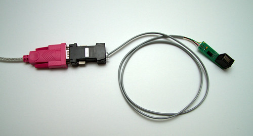
The RAVEn is a USB device that provides a USB serial port, on that port are XML messages. My script takes those XML messages and writes them to MQTT as JSON. Is there something else that I could plug the RAVEn into to do this, something that I can place close to the smart meter?
I’m a fan of using ESP8266 devices in the D1 mini form factor for my current home automation. Could I use one of these to build a RAVEn to MQTT bridge over wifi? Maybe, but with some caveats and possibly some effort and delay waiting for parts.
Other Arduino based options seemed just has hard so I turned to the old Raspberry Pi I had sitting around. I had previously used this to test out Kodi so I instead loaded up Raspberry Pi OS Lite and quickly found that I could transfer my existing perl script over, tweak it a little bit, and have it working.
The next hurdle with this as a solution was that it used wired ethernet and I don’t have wired ethernet in the room near the smart meter, I would need wifi if I wanted to have the RAVEn as close as possible.
What would it take to add wifi to this Pi? A USB wifi adapter can be used, but which one and how much would that cost? Would a cheap $8 adapter work, or would I have to get a $50 adapter? As well as not working, it might take a while for a cheap adapter to be delivered.
What about a newer Pi that included wifi? The Pi 3 B+ that I am using for Kodi has wifi even though I am using it on a wired connection, but that also costs towards the $60 mark, and seems to be out of stock.
Hold on, what about a Pi 3 model A+? This is smaller and cheaper than a B+, it also has wifi and the single USB port is fine for my single RAVEn. An online order and a few days later it arrived and was quick to get functional:
This has been running like this for about 36 hours now, taped the wall which puts it about 1 metre from the actual smart meter. Time will tell if this solves the reliabilty issues, but it is looking promising.
Of course this does seem like a bit of an overkill to use a whole Pi for this simple task. I might consider a Pi Zero, but I would need the W version (for wifi) and when you include the USB OTG cable the price is getting closer to that of the A+, and these are sold out everywhere I checked…
The final thing I want to mention today is that after I cleaned up my script I also wrote up some documentation and pushed it up to GitHub:
Just don’t yet look at my other repos as all you will see are two that were created seven years ago, only one of which has any code pushed to it. One of the items buried on my todo list is to clean up and push some of the other things I have written for my home automation setup…
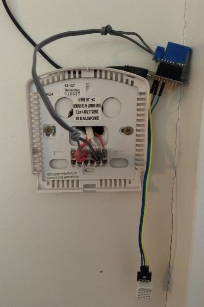
On days when it is cold enough for my central heating to be needed in the morning but then it warms up for the afternoon I will leave my laundry door (and sometimes the front door) open (there are screen doors as well) to allow for plenty of fresh air. However I didn’t want the central heating to come on while the door was open as that would be a waste of energy.
Before I hooked my heating into my home automation I acheived this by flicking the HEAT/OFF switch on the thermostat, and for the initial implementation of my Arduino based controller it was easy to disconnect the relay was it was only connected with an alligator clip. However I recently mounted this controller to the wall in a more permanent way:
I couldn’t just pull the power on it as I still wanted the temperature readings, and altering the schedule in Google Calendar wasn’t that convenient, so with all the extra time I am now spending at home I decided to implement one of the things from my todo list: a sensor on the back door.
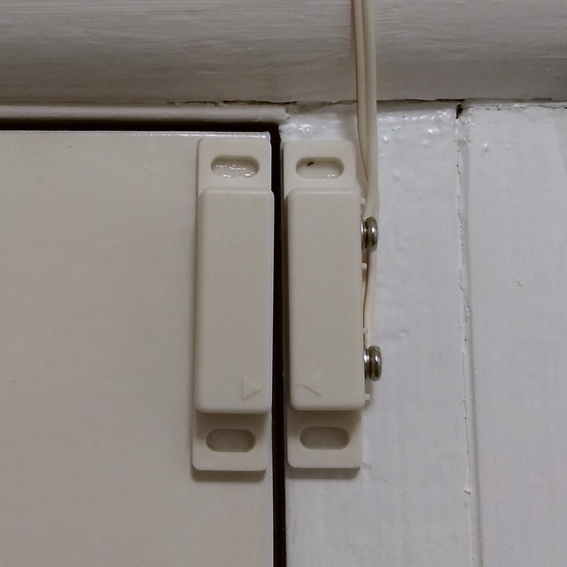
Some time back I had picked up some magnetic reed switches (like used in an alarm system) and it was straightforward to connect that up to one of the digital inputs on the D1 mini to read the state. It was a little bit more work to work out what and when to sent MQTT messages but that was easy to reverse engineer from the MQTT Binary Sensor config for Home Assistant.
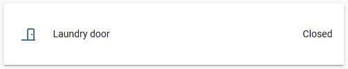
I could now stand at the door with my phone, opening and closing it, and seeing the state change in the Home Assistant interface.
Though knowing if the door is open is only one part of the puzzle, I need to interact with the thermostat component.
I had two automations to drive the thermostat from the calendar:
when a heating event starts THEN turn on the thermostat component and set the target temperature
when a heating event ends THEN turn off the component and set the target temperature to zero
I altered these and added new automations to end up with:
when heating event starts AND door is closed THEN turn on thermostat
if door open for 5 minutes AND thermostat is on THEN turn off thermostat
if door closed for 5 minutes AND thermostat off AND during heating event THEN turn on thermostat
when heating event ends THEN turn off thermostat
This seems to be working. I put in the 5 minutes condition as I only want it to be when I have deliberately left the door open, not if I open it briefly, eg to put something in the bin. I think I might be able to combine the automations into only two, but I will leave that for later.
I also plan to have a proper outdoor temperature sensor so that I can have it notify me if the temperature is dropping and I have left the door open, or also if the temperature has risen enough that I might want to open the door.
But first I will cross a different item off my todo list, one that involves two microswitches and my garage door…
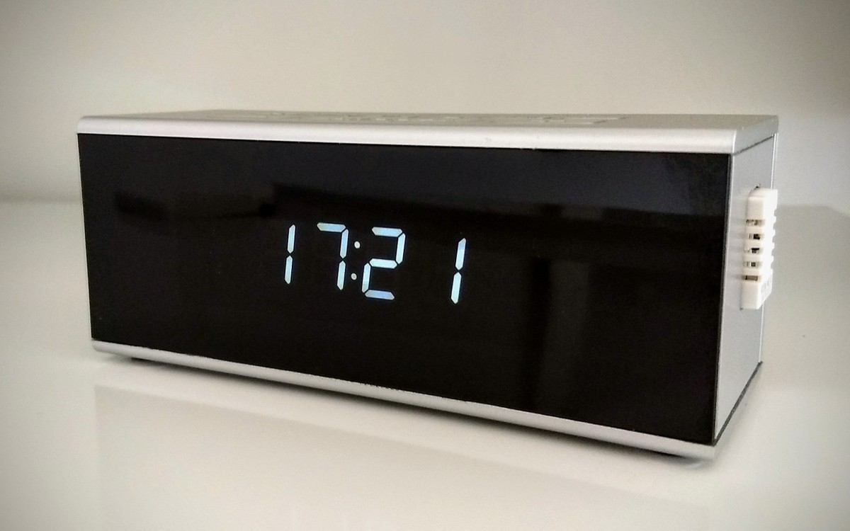
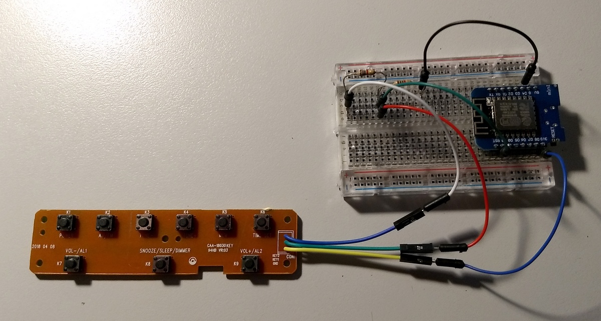
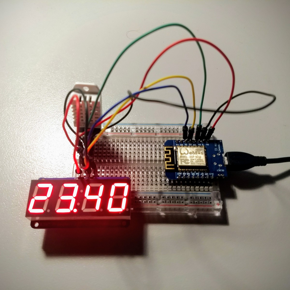
Around my house I now have three not a clock devices, in addition to one in my bedroom and another in the kitchen, the newest one in my study.
I mentioned in the earlier post how I retained the power connector so I could easily reuse the 5V power supply that the clock came with. I also left the circuit board for the buttons attached, partially to keep the buttons in place but also for potential future use.
In putting together the third one for my study I decided to see if it was possible to connect up the buttons. Spoiler: it is.
There are nine buttons that are connected by three wires. Looking closer I found that there is a common connection and then the buttons in two groups as resistor ladders, where each button corresponds to a different resistance.
The D1 mini only has a single analogue pin so I was initially concerned that I would only be able to connect half of the buttons, but after some experimentation I found that I could connect one group directly to the analogue pin and then the other group via a resistor. I don’t know what the resistances are, just that in the 0-1024 range of the analogue pin I was getting a decent spread of values.
The analogue values were not quite stable, fluctuating a bit, so in my logic I declared a set of ranges that mapped to each button. From this logical button state (nine buttons plus no button) I applied some de-bounce logic and had the arduino send an MQTT message when a button was pressed:
home/study/button POWER
home/study/button TUNEDOWN
home/study/button TUNEUP
home/study/button MEM
home/study/button SET
home/study/button VOLDOWN
home/study/button SNOOZE
home/study/button VOLUP
This worked, but wasn’t quite right as sometimes the button press didn’t seem to be registered and there would be MQTT connection issues. So it was registering the button, but it was failing sending the message. After some research I found that this was due to a limitation of the ESP8266. It is a nice small and cheap controller, but that single analoge input is also shared with the wifi chip, by constantly reading the analogue input I was causing the wifi to drop out.
The recommendation I found was to introduce a delay into reading the analogue input. So instead of reading the analogue input every time through the loop(), it will only check again after a specified interval. My debounce logic required the button to maintain the same state for 50ms, so I put in a read interval of 10ms and it worked perfectly.
Now a button is only part of a solution, what would I be controlling? Right now I don’t really have anything I want to control, in the future I plan to automate the tilt of my window blinds, but to prove the concept I added automations to home assistant to control the radio:
This worked and as I have three devices with these buttons, so instead of tying the automation to a specific device I used the + wildcard so it would trigger on any of them.
Next I need to get around to building things (such as the blinds controller) that can be triggered…
Up until yesterday the last change I made to my script that pulls usage information from my smart meter was to make it use a serial port library. At the time I grabbed the example and apart from adding in a hack to remove the null characters I was getting it worked fine.
Inspired by some things at LCA2020 last week I decided that I would change how I was getting the usage data.
The adapter I am using appears as a serial port and while you can send commands, if you just read from the serial port it will output an InstantaneousDemand XML payload every few seconds. The script I was using would connect to the serial port and read until it got one of these payloads (erroring if it didn’t see one in 30 seconds), writing the data to MQTT for Home Assistant to pick up.
This didn’t seem to be the best way, it sometimes wasn’t able to open or read from the serial port (one hung process could give hours of errors) and it was also skipping over information.
My replacement version would instead run as a daemon, connecting to the serial port once and then publishing MQTT messages whenever an InstantaneousDemand payload appears on the serial port. I still had it die if no payload had been seen for 30 seconds, but it would be restarted as I set it up as a service.
This was working quite nicely for a few hours, but then I noticed the load value was high, checking with top I found that this process was taking 100% of CPU. This wasn’t right…
Upon checking the documentation for Device::SerialPort I found that while I had used examples from the SYNOPSIS section, there was a full EXAMPLE that was much better.
In my loop I was trying to read() a single byte each time, instead I should be reading more bytes. The example used 255, so I went with that.
I wasn’t checking the count of bytes returned from read(), this explained the null data I had been seeing. I was reading when no data was available, if the count was zero there was no data.
There is a timeout value that controls how long the read will wait before returning zero data. If not set then the loop in my code would be calling read() as fast as it could, setting this to one second meant it was handled within the serial port library.
After making these small changes (aka using the library correctly) the CPU usage of this process dropped to nothing. While it wasn’t actually impacting the performance, it is good to do things properly.
Something else I an trying with this process is setting an MQTT Last Will and Testament message. This is a message that you set up when connecting to your MQTT server, but it will only get sent if there is an ungraceful disconnect. Coupled with a startup message I can get a notification when the process is starting and a notification if the process crashes. Time will tell how useful this will be, but it is interesting to learn about.
Power and internet comes into my home above my bedroom window. There have been a few times I have been laying in bed watching the cables whip around in the wind, wondering what damage that could be causing and how long the cables should last. This has in part been answered for me as the power cable (likely from when this place was built around fifty years ago) has now been replaced.
Tonight’s events possibly started around 8PM when I started to make some dinner, with one thing on the stove I started another in the microwave, at which point the kitchen lights dimmed (more than ever before) and in my study the UPS started to beep. For a while I had been tracking under voltage in my power because often the UPS would be boosting from battery, this time the voltage had dropped enough that the UPS was still able to boost, but also wanted to start shutting things down. Luckily I was done with the stove and microwave, once they were off the voltage was back to ok levels and the UPS was happy.
After I ate my dinner I started to check my logs and research who to contact about this, then my phone rang. It was my neighbour from the other unit asking if my power was on, because hers was not. This was unexpected as our units are semi-detached, we share the same power cable and the meters are in the same box. But then my power also went out.
Heading outside to talk we saw that the streetlights were on and that other houses in the street still had power. In the meter box I saw that both of our meters were on, so had our power been turned off remotely?
United Energy is my electricity distributor, nothing was listed on their outage page and as I was looking for a faults number to call I received a call. It was someone from United Energy to tell me that my power had been switched off as they had detected a fault. They asked some questions around if I had noticed any issues (I said I had) and told me that a work crew had already been requested and should be there some time that evening.
About an hour later the crew arrived, two people, one in a van and the other in a bucket truck. There were not the friendliest of people (they did have a job to do after all) but from what I could gather they identified the cable as old so would be the likely issue. An hour later they had replaced the cable and run some tests, my power was now back on and they were gone.
I mentioned that I was checking my logs, so what logs do I have?
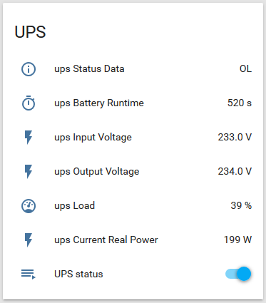
After I resolved the issue of my UPS shutting down every few weeks I noticed that something was happening to cause the fans in the UPS to come on. The UPS is connected via USB to my linux box but all I was logging was the power output every five minutes. Adding the UPS component into Home Assistant gave me a nice view (and history) of a number of values:
I set up an automation to notify me (via Pushover) whenever the status changed. Over time I was able to see that the UPS was detecting a drop in input voltage, so was using the batteries to boost back up to a normal level. This would typically happen if I used two large applicances at the same time (eg washing machine and stove), but also at other times as well. It was on my todo list to find out what the acceptable voltage range was and probably get it looked at.
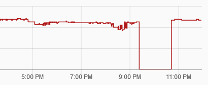
So what was the voltage doing tonight? This:
A few things can be seen:
Around 230V before 5PM when I wasn’t home
Initial drop to around 210V as I put my hot water on boost, then sitting around 220V
Big drop to 200V and then as low as 180V around 8PM
No data when the power was off
Back to 233-239V once I turned everything back on
I will continue to monitor the UPS status with the expectation that I should not (or at least rarely) get notified about undervoltage again.
The final thing I want to say now is that this has been an interesting coincidence. The reason I needed to boost my hot water was because it had been turned off all week while I was at LCA2020 where the overall theme was security and privacy. The specific coincidence I am thinking of is that there was one talk about the smart meters (I hadn’t realised that outside Victoria the rollout was still ongoing and contentious) and I was part of a couple of discussions about their advantages and disadvantages. In this case the remote detection of a fault and quick rectification was a good thing.
Many years ago I started monitoring the power consumption of my house via a ZigBee dongle that communicates with my smart meter. The quick and dirty solution I did at the time stayed in place for a long time, until it started to play up…
The first symptom I noticed was that my script would hang, in itself not that bad, except that I was calling it directly from MRTG… which would cause the entire MRTG polling loop to hang, so I wouldn’t get any monitoring. In response I split the script, one to read the usage to write to a log, and another (called by MRTG) to read the latest entry in the log.
The reading script would still get stuck, so I added a generous timeout and stopped thinking about it. Until I thought it would be a good idea to also drop the usage data onto MQTT for Home Assistant to grab. Nothing wrong with this, except that I upped the frequency from once every five minutes to every minute. Sometimes it would fail for hours, sending an email with the error every minute…
I initially noticed the increase in timeouts around the same time that I upgraded the hardware in my linux box and did a fresh install of Ubuntu. Due to default permission changes I found that I could no longer simply cat the serial port, I needed to connect using Device::SerialPort, so I was thinking that there was something wrong with the usb-serial chipset or the driver.
That was until a few weeks ago, when I upgraded the hardware in my Windows desktop.
For a long time I have been aware of a slight ticking sound coming from that computer, you know the sound of a fan slightly hitting something or being slightly off balance?
The new build went great and although I didn’t really need the upgrade it let me do an upgrade that was required, to my parent’s computer. As I was handing down parts I thought that I could replace the power supply fan instead of buying a whole new power supply, so I powered it up and heard the same noise…
… coming through my speakers.
Oh, this is not a bad fan, this is a failing power supply.
So what does serial port problems in one computer have to do with a bad power supply in another one? Probably nothing, but since replacing that power supply I haven’t had a single timeout error, it is as stable as when I first picked up the adapter. I guess it is possible that the power supply was generating interference at around 2.4GHz…
Another thing I didn’t think was related was that the UPS that these two computers run from had started to shut down. Not in any graceful manner, but with a sudden power off followed by a loud continuous beep. I suppose it is also possible that a bad power supply could also trip the UPS…
As is becoming a habit, January for me means attending linux.conf.au which this time around was held in Christchurch, New Zealand.
The theme this year was “The Linux of Things” and rather than paraphrase the definition I will simply quote part of it:
“Building on the role that Linux plays in our everyday lives, we will address IoT-related opportunities and concerns from the purely technical through environmental, health, privacy, security and more.”
Those who know or follow me should immediately spot that that this is strongly aligned with myrecententhusiasm for home automation. I lost count of how many conversations I had with people about what I had done and what they had done, then there were a number of relevant talks that added more information into the mix. It is a lot to think about…
A few of the bigger takeaways are:
Home Assistant is good for automation and displaying recent history, but store long term history elsewhere.
Use what you are comfortable with. For others this may mean off the shelf devices, but for me this means I will continue building simple functionality into arduinos.
What you actually do is also highly personalised. Just because someone triggers the aircon in their office to turn on when they make their first cup of coffee doesn’t mean that you have to as well.
Always learn from what other people have done, and just as importantly share what you have done so others can learn from you.
That last point isn’t really new or home automation related, it is part of the philsophy underpinning open source itself, so not surprising that it came up (a lot) at an open source conference ;)
As is also becoming a habit, I am not going to travel to another country just for one week, in a similar way that I followed up Hobart 2017 with a road trip, I am also following up Christchurch 2019 with a road trip:
I will need to hold off (for now) the planning a road trip from the Gold Coast, because that is where LCA will be in 2020…
Once I had my central heating controlled by Home Assistant based on a schedule in Google Calendar I started to think about how I could also control my stereo that I use as my alarm clock. This 25 cd stacker double tape desk stereo (purchase from Brashs gives an idea of how long I have had it) was the final clock in my house (I’m considering my car stereo to be out in the garage) that I would need to adjust for daylight saving.
My first thought was to find a manually tuned radio that I could just control the power of via a relay. I was able to find a few cheap radios, but they all had electronic tuners, so you couldn’t just kill the power. I also didn’t want to use an old radio, because it wouldn’t be as nice.
Next I started looking into playing back the infrared codes from the remote control for my stereo. This looked promising, but I was starting to like the idea of getting rid of the reasonably large stereo.
I briefly looked into a radio tuner module controlled by the Arduino. This would give me the ability to remotely tune to different stations, but it would also need some form of powered speakers that turned of/off at the same time.
Another option was a network speaker and I considered some cheap wifi speakers, but dismissed them when I found that nobody had integrated with them, I also didn’t find anything good said about the phone app they use for control. Also on the network speaker approach were options like a Sonos or a Google Assistant speaker. These are a lot more expensive and require cloud integration that I didn’t like.
The solution I went with was a network speaker somewhere in the middle, a speaker with integrated Chromecast. These have been discontinued in favour of more expensive models with Google Assistant, (I was able to find a new one on ebay for a very reasonable price) but with the advantage over a cheap speaker of there being a Google Cast component in Home Assistant.
Once setup on my wifi network it was again fairly straightforward to create automations to trigger playback from a network URL, the tricky part turned out to be finding the streaming URL for the radio station I wanted. If you go to there website the stream is provided by iheartradio which I couldn’t get to work, but I found a different source for the same station from the website of the radio network.
This has been working well (and I reclaimed space where the old stereo used to sit) but it does feel a bit wrong to change from receiving a broadcast over the air to downloading a network stream, it goes against one of my goals of not relying on internet/cloud services, although it can be rightly pointed out that using Google Calendar for the schedule already violates that goal…
I have gas ducted central heating with a controller mounted in a central location. You could say I didn’t need to change a thing as it was already “smart”:
Yeah, nah…
This is what is referred to as a 5+2 programmable thermostat, there are two sets of schedules, one for the five days of the week and another for the two days of the weekend. The interface between this thermostat and the heating unit itself a pair of wires carrying around 25VAC, close the circuit to turn the unit on, this would be done instead by a relay connected to an Arduino.
On the user interface side I was planning to use a Google Calendar as I could put in events to represent the schedule and I could already manipulate it from my phone the the web interface which covers off remote access. The regular schedule would be in as repeating events, but I could adjust them as needed if I knew I wasn’t going to be home until later than usual.
My original plan had been to write something that would query the google calendar and push that information to the thermostat Arduino which would compare the target temperature against the current temperature and set the state of the relay appropriately. This approached changed when I saw that there was a Generic Thermostat component in Home Assistant that would handle the logic of being a thermostat. I wouldn’t need to implement that on an Arduino, it could just be a dumb relay control for Home Assistant to turn on or off. As Home Assistant can use any type of switch component for this and I was already basing things around MQTT I looked at the MQTT Switch component.
I don’t really know how a switch should be implemented, but from the desired behaviour it was easy to work out that the Arduino would listen on a topic for a state (OFF/ON) and ideally it would publish the new (or current) state on another topic. An additional thing I added was a failsafe, the relay would timeout after five minutes, if something went wrong (eg wireless went down or Home Assistant crashed) I didn’t want the heating to run forever.
I did encounter one snag with the relay shield that I had, it was hardwired to have the relay on pin D1, but that was one of the default I2C pins. While I wasn’t using one of the I2C displays in this situation, I was trying to share code between my devices. Later versions of this relay shield let you configure which pin it uses, so in my case my I pulled out the D1 pin (I had already soldered it up) and ran a wire around to another pin.
Adding the switch logic to the Arudino sketch didn’t take long, nor did adding the configuration to Home Assistant, so it wasn’t long until I has it connected up for testing:
This worked well, so I moved onto implementing the scheduling aspect using the Google Calendar Event component and automations.
Despite parts of the documentation not matching the implmentation (I need to follow that up, possibly asking on the forum or even submitting a patch…) it wasn’t long until I had automations configured to set the target temperature when a calendar event started, and to then turn off the thermostat when the event ended.
It was now a waiting game as I needed to let the automations trigger over time, and I also needed the weather to cooperate. Fortunately I am in Melbourne where despite it almost being summer we had a week or so of cool enough weather for this to happen:
I was quite happy with this, just in time for summer to really kick in and I no longer have a need for central heating… but that does give me time to sort out a proper mounting and power supply. I was initially thinking about finding some kind of unobtrusive box to mount on the wall, but the idea of featuring the electronics (such as a Tripler Base mounted to a blank plate) is growing on me…
Do you see this thing that looks a lot like a bedside clock? While it may be displaying the current time, it is not really a clock…
To explain what I mean I need to go back a few weeks to when I was inspired to finally do something with the various electronic components I have collected over the years (five years since I plugged in a DS1820 sensor) for home automation. After some tinkering and relying heavily on the examples that come with the libraries I had this going:
On this breadboard is a D1 mini microcontroller, a DHT22 temperature and humidity sensor, and a 4-Digit 7-Segment Display from Adafruit. It is fantastic that other people have done the hard work of sorting out the libraries for the board (with wifi), the sensor and the display. Everything I have done with these is based on the examples provided.
What is happening in this photo is that it is alternating between displaying the temperature and the humidity, but over the following few weeks I continued to tinker until I had it publishing the temperature (and humidity) over wifi to an MQTT server in order to get the data into Home Assistant which displayed this:
Yes there are two data sources, because I had five (more on the way!) of these microcontrollers and they are cheap and simple enough to scatter around the house. They are easy to run from a USB charger, so anywhere I have a powerpoint I can have a device. I now have a lot more configured in Home Assistant and I am feeding in data from other sources, but they will be posts of their own, for I need to get back to explaining why this is not a clock.
Apart from adjusting to the time change, my biggest annoyance with daylight saving is the clocks that need to be manually changed. It is a lot easier these days as phones/computers/etc will automatically update, but I still have a few clocks that need to be adjusted.
My bedside clock is one of these and while I know you can buy a clock that adjusts automatically, when I last looked (it has been a while) I didn’t like the look of them and they were too expensive. So this was going to be my first project and at first I was going to make it a clock that would use time protocols to get the correct time, but you still needed to deal with timezones and other things.
So why not make it dumb? I have a linux box that is always on (where I am running services such as Home Assistant) and it has already dealt with the timezone and DST changes. Every minute it could publish what it thought was the current local time, something as simple as cron running a bash script:
The requirements for the “not a clock” are pretty simple:
Connect to wifi and the MQTT server, subscribe to the home/localtime topic
Every 60 seconds publish temperature/humidity to MQTT (for Home Assistant to collect)
Whenever a message arrives on the home/localtime topic, output to the LED display
Making enclosures is probably what I will have the hardest time with (do I buy a 3d printer?) and until this evening I had bare electronics hanging from the wall in four locations around my house. With the need to be able to see the LED display I had the idea of using a clock radio as the enclosure. I decided against gutting my working clock radio so over the weekend I stopped by the local Kmart where I found a clock radio for the lofty price of $15:
(I’m showing the silver model as the picture gives a better idea of what it is, the black model is just a black obelisk, it also comes in rose pink if that suits your colour scheme)
It is not designed to be opened up so some force was required, but after removing the internals and the strategic application of tape and hot glue I have what is in the top picture. I have the temperature sensor taped to the side because I think it wouldn’t get the best reading being inside the case, limited airflow and some heat from the electronics could skew the reading.
An unexpected bonus of this specific radio (and it makes sense from an electrical certification point of view) is that it runs from 5 volts and comes with a small power supply. I retained the socket for this and wired it up to the D1 mini instead of using a USB power adapter. I also kept the board for the buttons on the top of the clock, in the future it might be nice to use them to as a trigger for some action…
I have a lot more to say about Home Assistant, including how I am testing out control of my central heating (just in time for summer…) using a D1 mini equiped with a relay. I have also realised that the remaining clock I have to manually adjust for daylight saving is my stereo, the 25 cd stacker double tape desk stereo that I use as my alarm to play the radio… is there a wifi speaker in my future?
When I recently started monitoring temperature it involved a USB to RS-232 adapter connected to my Linux box. A few weeks later I plugged in a USB device to monitor power usage.
Temperature was via /dev/ttyUSB0 and power was via /dev/ttyUSB1. Until an unscheduled reboot at which point they swapped around as that was the order the devices are detected at boot, not the order in which they were plugged in.
A quick search led me to discover that you can write rules for udev to give devices persistent names.
Relying heavily on Writing udev rules I muddled through enough to end up with these rules:
While some people are heavily against smart meters, I am not concerned. In fact when I received the initial notification about the installation my first thought was about the possibility of playing with new technology.
When they finally installed the meter it coincided with a co-worker getting solar panels installed which led to a number of conversations about ways to monitor power generation and consumption. Based upon previous research I had done I knew that other people in Melbourne had had success with Rainforest Automation devices which use the ZigBee Smart Energy wireless protocol to connect to the smart meter.
My co-worker opted for the EAGLE as his solar panels also connected over ethernet, while I opted for the (cheaper) RAVEn which is a USB dongle.
Once the devices arrived I had to wait a few more days until my smart meter was completely setup, but then it was a simple matter of entering the address and install code from the RAVEn into the online portal for the smart meter. After a quick test with the windows app, I plugged it into my Linux box to see it come up as a serial port.
It was nice to simply run cat /dev/ttyUSB1 and see it output an XML fragment reporting the instantaneous demand every few seconds.
The documentation for the XML API showed me how to send commands and how to convert the hex values to decimal and how to apply the multiplier and divisor. It didn’t take long to wrap this in a script to be called by MRTG:
Events visible in this sample include:
Hot water turning on at 11PM AEST and topping up a couple of times
Fan and light while getting ready for work
Fridge cycling on during the day
Use of oven to cook dinner
Lights and other usage when I am at home
Due to complications with having off-peak electric hot water (aka a ‘controlled load’) I do not get summation values, instead that is just a graph of the instantaneous load. So while it doesn’t give true usage, it is a good enough indicator.
Currently this graph is available to anyone who knows the URL, and while it can let someone determine when I am or am not at home, the easier way to do that would be to go into my backyard and look through a window.
Ten years ago I purchased a couple of DS18S201-Wire temperature sensors to monitor the outdoor temperature, the ambient room temperature and the temperature inside my computers. Along with the sensors themselves I got a RS-232 to 1-Wire adapter and a DS1820 mounted on a demo board.
While I did connect them up and used DigiTemp to prove that the adapter and sensors worked. I didn’t get much further, until two months ago when I decided it was about time to do something related to home automation, the result being this:
producing this:
After a failed attempt at using an old serial port header to connect the RS-232 adapter I splurged on an entire $6 to get a bright pink USB to RS-232 adapter. The remainder of the hardware pictured is the DS9097U-009 adapter and the demp DS1820 mounted at the end of an RJ11 cable.
The software side consists of the digitemp package, a wrapper to pull the temperature from the digitemp output, and my existing MRTG setup.
Since then this setup has been logging the temperature every five minutes. It was interesting to be able to see my central heating come on at 5pm and cycling to maintain a target temperature of 20°C until 11:45pm. The above snapshot shows the central heating coming on yesterday, but not on the current day.
Despite this now being in use for almost two months, my plan is to incorporate the sensors into something more sophisticated, for example an Arduino based ethernet connected thermostat for my central heating. This is not a new idea, there are just a couple of examples floating around to use for inspiration.