Pressing buttons
Tuesday, January 28th, 2020 at 09:12pm
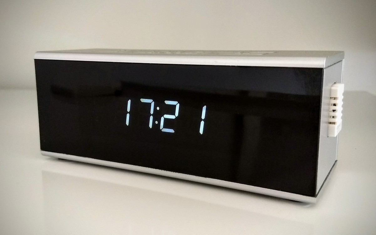
Around my house I now have three not a clock devices, in addition to one in my bedroom and another in the kitchen, the newest one in my study.
I mentioned in the earlier post how I retained the power connector so I could easily reuse the 5V power supply that the clock came with. I also left the circuit board for the buttons attached, partially to keep the buttons in place but also for potential future use.
In putting together the third one for my study I decided to see if it was possible to connect up the buttons. Spoiler: it is.
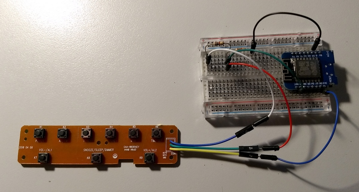
There are nine buttons that are connected by three wires. Looking closer I found that there is a common connection and then the buttons in two groups as resistor ladders, where each button corresponds to a different resistance.
The D1 mini only has a single analogue pin so I was initially concerned that I would only be able to connect half of the buttons, but after some experimentation I found that I could connect one group directly to the analogue pin and then the other group via a resistor. I don’t know what the resistances are, just that in the 0-1024 range of the analogue pin I was getting a decent spread of values.
The analogue values were not quite stable, fluctuating a bit, so in my logic I declared a set of ranges that mapped to each button. From this logical button state (nine buttons plus no button) I applied some de-bounce logic and had the arduino send an MQTT message when a button was pressed:
home/study/button POWER
home/study/button TUNEDOWN
home/study/button TUNEUP
home/study/button MEM
home/study/button SET
home/study/button VOLDOWN
home/study/button SNOOZE
home/study/button VOLUP
This worked, but wasn’t quite right as sometimes the button press didn’t seem to be registered and there would be MQTT connection issues. So it was registering the button, but it was failing sending the message. After some research I found that this was due to a limitation of the ESP8266. It is a nice small and cheap controller, but that single analoge input is also shared with the wifi chip, by constantly reading the analogue input I was causing the wifi to drop out.
The recommendation I found was to introduce a delay into reading the analogue input. So instead of reading the analogue input every time through the loop(), it will only check again after a specified interval. My debounce logic required the button to maintain the same state for 50ms, so I put in a read interval of 10ms and it worked perfectly.
Now a button is only part of a solution, what would I be controlling? Right now I don’t really have anything I want to control, in the future I plan to automate the tilt of my window blinds, but to prove the concept I added automations to home assistant to control the radio:
- alias: Button play radio
  trigger:
    - platform: mqtt
      topic: home/+/button
      payload: "POWER"
  action:
  - service: script.radio_play
- alias: Button stop radio
  trigger:
    - platform: mqtt
      topic: home/+/button
      payload: "SNOOZE"
  action:
  - service: script.radio_stop
This worked and as I have three devices with these buttons, so instead of tying the automation to a specific device I used the + wildcard so it would trigger on any of them.
Next I need to get around to building things (such as the blinds controller) that can be triggered…
Tagged with: home automation
