A flurry of PCB design
Sunday, July 21st, 2024 at 02:56pm
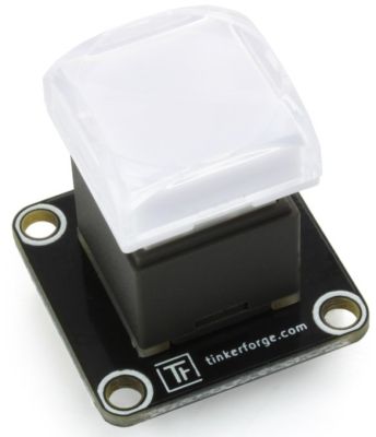
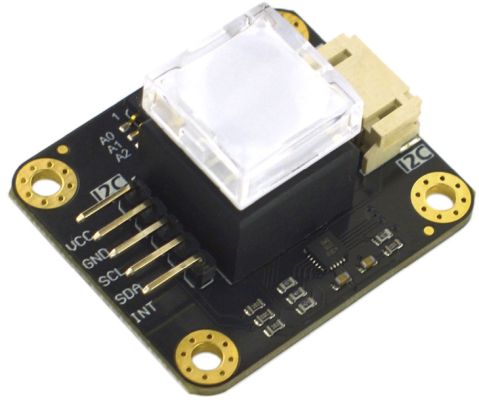
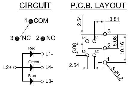
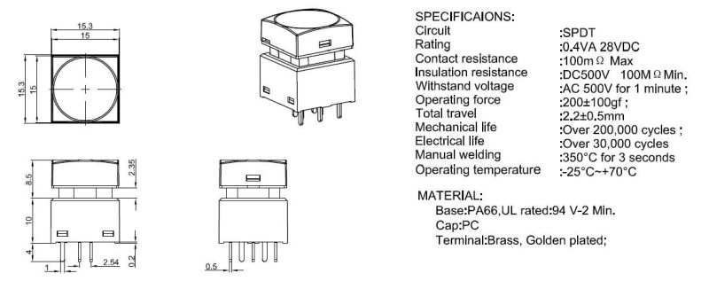
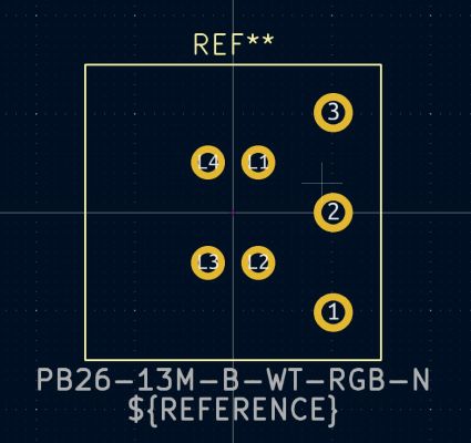
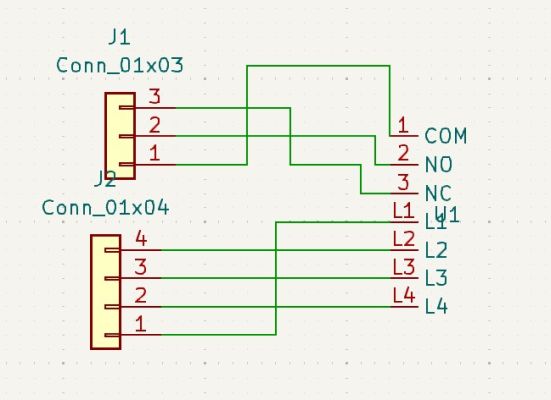
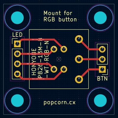
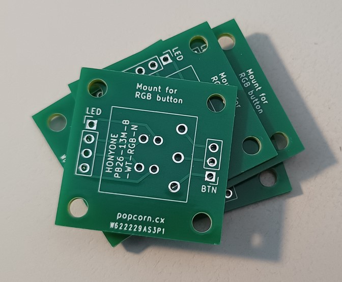
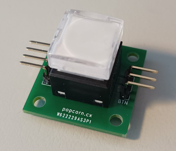
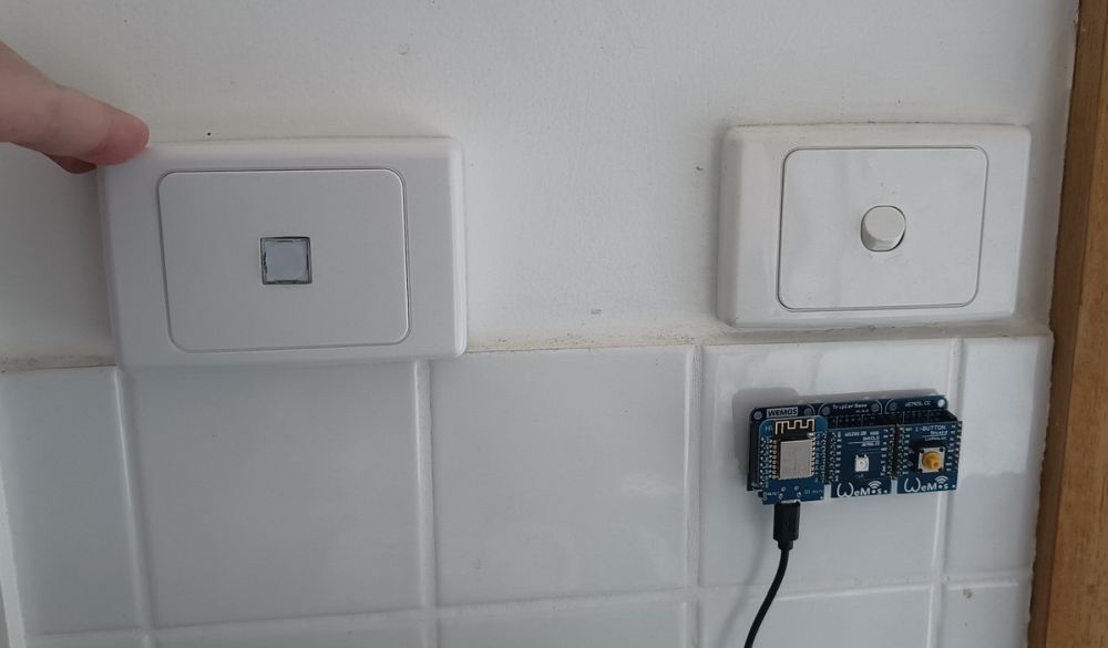
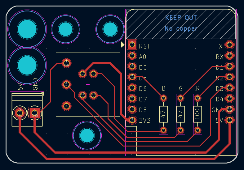
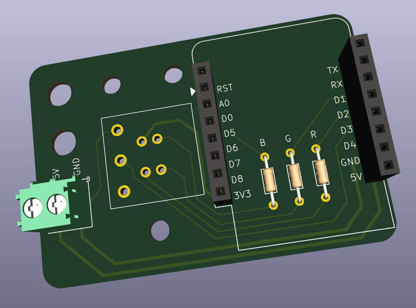
After the success of designing and ordering my first custom PCB I continued on with designing a board to hold the RGB button and microcontroller behind the faceplate. This time I was able to use existing footprints for the D1 mini, resistors and a terminal block for power:
When I went to order these boards I realised that postage for a small order was most of the cost, but I could add other boards to the same order for the same postage cost. I was already planning on adding another not a clock to the lounge room, so why not order boards for that instead of hand soldering more proto boards:
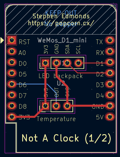
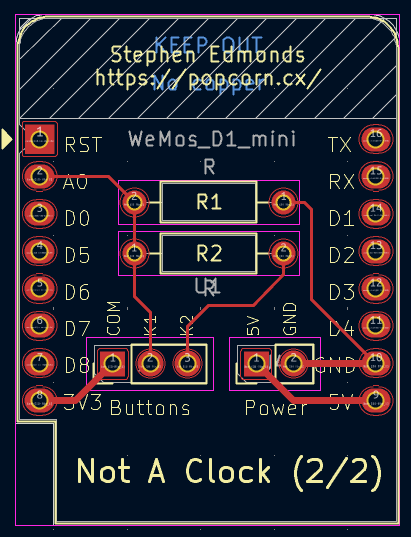
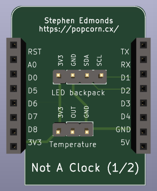
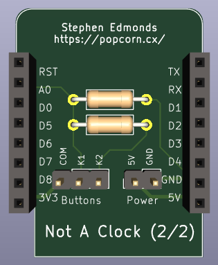
I maintained the same D1 sheild PCB size as that fits nicely within the clock enclosure and I did try designing the two pieces to be a single board that you would break into two, but I couldn’t quite figure that out, so separate boards was the end result.
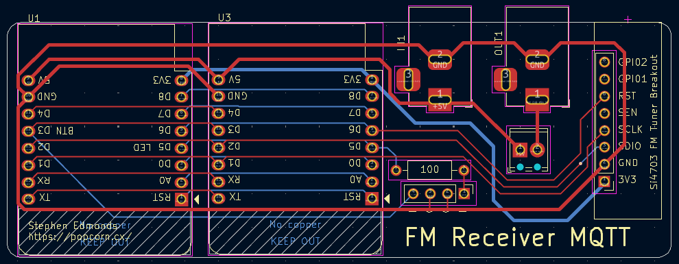
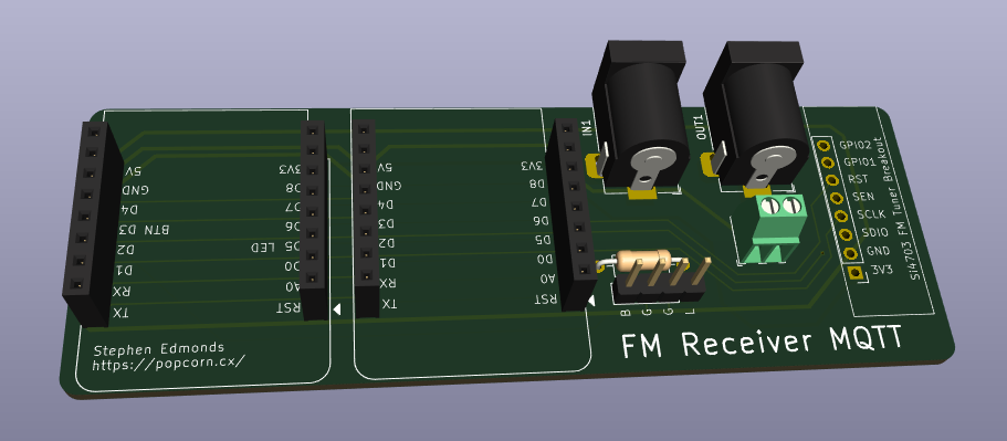
As I was getting more comfortable with KiCad I moved on to a more ambitious (for me) project, a PCB for my MQTT controlled FM radio. At this point I decided to keep using the relay shield, so I needed two sets of D1 mini headers, power in, power out via the relay, a button, an LED indicator and of course the FM module:
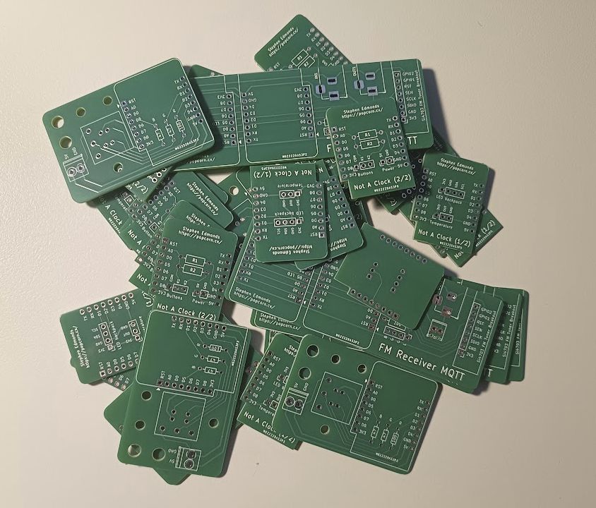
I felt that four different PCB designs was enough to split the postage over, so I submitted the order and today received a satisfying delivery:
Tagged with: home automation, kicad